|
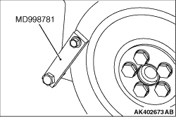
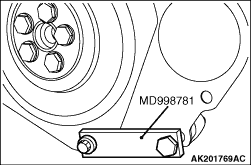
1.Using the special tool Flywheel stopper (MD998781), hold the flywheel in place.
2.Remove the flywheel bolts.
|
|
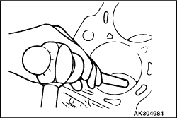
| caution |
Pay full attention not to damage the cylinder wall. Using the
metallic bar of the appropriate length, strike to the oil jet.
|
|
|
Until reaching the bottom, strike the oil jet from the crankshaft journal using the pin
punch whose diameter is 4.5mm.
|
|
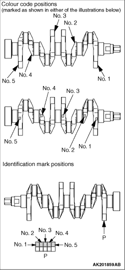
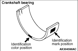
1.Measure the crankshaft journal diameter and select bearings according to identification
marks or color codes given in the table below. The journal diameter can be identified if the
crankshaft is provided with identification markings in the illustrated positions.
Bearing Selection Table
|
Crankshaft
|
Cylinder block identification mark
|
Bearing identification mark
|
Identification color or mark
|
Journal diameter mm
|
Yellow or 1
|
47.994 - 48.000
|
0
|
1
|
1
|
2
|
2
|
3
|
No color or 2
|
47.988 - 47.994
|
0
|
2
|
1
|
3
|
2
|
4
|
White or 3
|
47.982 - 47.988
|
0
|
3
|
1
|
4
|
2
|
5
|
|
|
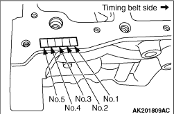
2.Cylinder block bearing bore diameter identification marks are stamped in the positions
shown, starting with No. 1 from the timing belt side.
|
|
3.Based on the identifiers verified in steps 1 and 2, select bearings from the table above.
(1)
<Bearing selection example>
(2)
If measured crankshaft journal diameter is 48.000mm, it means yellow in crankshaft
color code or 1 in crankshaft identification mark.
(3)
Based on the above, if the cylinder block bearing bore diameter identification mark
is 1, select a bearing with an identification mark of 2.
|
|
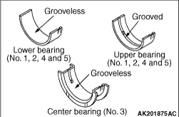
4.Install grooved bearings to the cylinder block.
| note |
Center bearings (with thrust flanges) are grooveless.
|
5.Install grooveless bearings to the bearing caps.
|
|
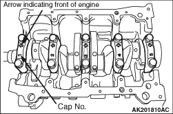
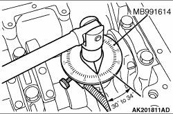
1.On the bottom surface of each bearing cap is the cap’s number and an arrow. Starting
at the timing belt side, fit the bearing caps in numerical order. Ensure that the arrows point
toward the timing belt side.
2.Apply engine oil to the threaded portion and bearing surface of the bolt.
3.Tighten the bolts to the specified torque of 34 ± 2 N·m.
|
|
4.Using the special tool Angle sensor (MB991614), tighten the bolts to a further 30° to
34°.
|
|
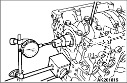
5.After fitting the bearing caps, measure the end play in the crankshaft. If the measurement
exceeds the specified limit, replace the crankshaft bearings.
Standard value: 0.05 - 0.18 mm
Limit: 0.25 mm
|
|
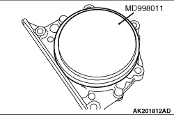
Press-fit the rear oil seal using the special tool Crankshaft rear oil seal installer
plate (MD998011).
|
|
|
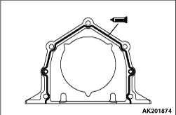
1.Remove completely old FIPG remaining on the rear oil seal case and cylinder block
(oil seal case mounting surface).
|
|
2.Apply a bead of FIPG to the surface of the rear oil seal case as shown in the illustration.
Specified sealant:
Three bond 1207F or equivalent
3.Install the oil seal into the cylinder block after applying an appropriate amount
of engine oil to the entire circumference of its lip portion.
4.Install the rear oil seal case by tightening its bolts to 11 ± 1 N·m.
|
|
1.Using the special tool Flywheel stopper (MD998781) secure the flywheel.
2.Tighten the flywheel bolt to the specified torque of 132 ± 5 N·m.
|
)

)
)
)
)
)
)
)
)
)
)
)
)
)