|
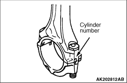
Mark the cylinder number on the side of the connecting rod big end as a guide for reassembly.
|
|
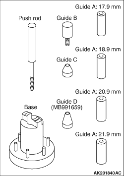
1.The special tool Piston pin setting tool (MD998780) consists of the elements shown
in the illustration.
2.When removing the piston pin, the special tool Guide D (MB991659) is also used.
|
|
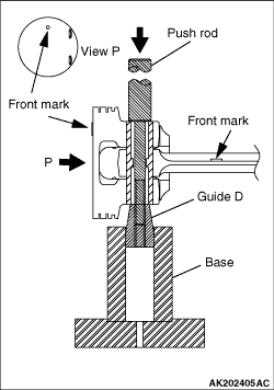
3.Insert Push rod, into the piston from the front mark side, then attach Guide D, to the
push rod.
4.Place the piston and connecting rod assembly on Base, with the front mark facing up.
5.Use a press to remove the piston pin.
| note |
Keep the disassembled pistons, piston pins and connecting rods per cylinder.
|
|
|
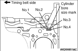
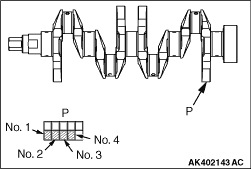
1.When replacing a piston, check the cylinder bore size mark stamped at the indicated location
on the cylinder block and select an appropriate replacement piston using the following table.
|
|
Cylinder bore size mark
|
Piston size mark
|
A
|
A
|
B
|
B
|
C
|
C
|
|
| note |
The piston size mark is located on the piston top surface.
|
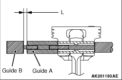
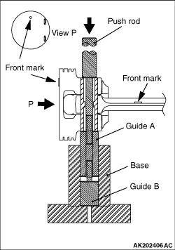
2.Insert the push rod into the piston pin and install the guide "A."
3.Align the front mark of the piston with that of the connecting rod. Align the piston
with the connecting rod.
4.Apply engine oil to the outer circumference of the piston pin.
5.Insert the piston pin guide "A" installed at Step 2 into the pin hole from the front
mark of the piston.
|
|
6.Screw the guide "B" into "A" until the clearance "L" reaches 2.25 mm between "A" and "B."
|
|
7.Place the piston and connecting rod assembly onto Base, with the front marks facing up.
8.Install the piston pin using a press. If the required press force is less than the
standard value, replace the piston and piston pin assembly or the connecting rod, or both.
Standard value: 4,900 - 14,700 N
|
|
|
1.Fit the oil ring spacer into the piston ring groove.
Install the upper side rail, then the lower side rail.
|
|
| caution |
Use of ring expander to expand the side rail end gap can break
the side rail, unlike other piston rings.
|
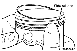
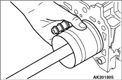
2.To install each side rail, first fit one end of the rail into the piston groove, then
press the remaining portion progressively into position by finger as shown in the illustration.
3.Make sure that the installed side rails move smoothly in either direction.
|
|
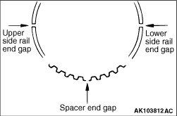
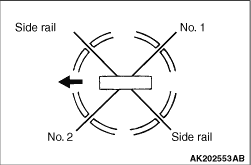
4.Locate the side rail and spacer end gaps as shown in the illustration.
|
|
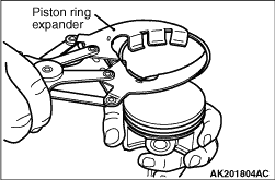
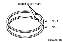
Using a piston ring expander, install the piston rings with their identification marks
facing up (toward the piston crown).
Identification marks
No. 1 ring: 1R
No. 2 ring: 2R
|
|
|
1.Apply engine oil generously to the piston’s outside surface, piston rings,
and oil ring.
|
|
2.Align the end gaps of the piston rings and oil ring (side rails and spacer) as shown in
the illustration.
3.Insert the piston and connecting rod assembly from the top of cylinder with the front
mark on the crown toward the timing belt side.
|
|
4.Use a piston ring band to hold the piston rings compressed when inserting the piston and
connecting rod assembly into the cylinder.
|
|
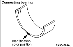
1.When replacing the connecting rod bearing, select a bearing of the size appropriate for
the crankshaft pin diameter in accordance with the crankshaft pin and connecting rod bearing
matching table shown below.
|
|
Bearing Selection Table
|
Crankshaft
|
Connecting rod Identification mark
|
Bearing identification color
|
Identification mark
|
Pin diameter mm
|
A or I
|
41.994 - 42.000
|
A
|
Red
|
None
|
Black
|
C
|
None
|
B or II
|
41.988 - 41.994
|
A
|
Black
|
None
|
None
|
C
|
Green
|
C or III
|
41.982 - 41.988
|
A
|
None
|
None
|
Green
|
C
|
Blue
|
|
|
|
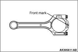
2.The identification mark of the connecting rod is found in the position shown in the illustration.
|
|
3.Select bearings from the bearing selection table in accordance with the identification
marks and color codes checked at steps 1 and 2 above.
(1)
<Bearing selection example>
(2)
If the measured outside diameter of crankshaft pin is 42.000 mm, the identification
mark are "A" and I, respectively.
(3)
Based on the above, if the identification of the connecting rod is "A," select the
bearing color in Red.
|
|
1.Install the bearing cap on the connecting rod while aligning the marks made during disassembly.
If the connecting rod is new and has no alignment mark, assemble it with the cap such that the
both bearing locating notches are on the same side as shown in the illustration.
|
|
2.Make sure that the thrust clearance of the connecting rod big end is proper.
Standard value: 0.10 - 0.25 mm
Limit: 0.4 mm
|
|
|
1.The connecting rod cap bolts and nuts are tightened using the torque-to-yield method.
For this reason, each bolt to be reused must be checked for elongation before installation. Whether
or not the bolt has been elongated can be determined by running a nut with fingers through all
the threads of the bolt. If the nut does not turn smoothly over all the threads, the bolt has
been elongated and must be replaced.
|
|
|
2.Apply engine oil to the threads and bearing surface of each nut before installation.
|
|
|
3.Finger-tighten the nuts on the bolts, then tighten the nuts alternately and repeatedly
to install the cap properly.
|
|
|
4.Tighten the nuts to a torque of 17 ± 2 N·m.
|
|
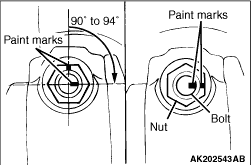
5.Make a paint mark on the head of each nut.
6.Make a paint mark on the bolt at a point 90° to 94° away from the
paint mark made on the nut in the tightening direction.
| caution |
- If the tightening angle is less than 90°, adequate tightness
could not be assured.
- If the tightening angle exceeds 94°, loosen the nut completely and
then perform the tightening procedure again beginning with the first step.
|
7.Turn the nut 90° to 94° to bring the mark on the nut into alignment
with that on the bolt.
|
)

)
)
)
)
)
)
)
)
)
)
)
)
)
)
)
)
)