|
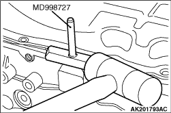
1.Remove the oil pan mounting bolts.
2.Knock the special tool Oil pan remover (MD998727) between the oil pan and cylinder
block as shown in the illustration.
3.Tapping the side of the special tool, slide the tool along the oil pan/cylinder block
seal and thus remove the oil pan.
|
|
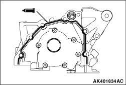
1.Completely remove existing form-in-place gasket from the cylinder block (oil pump case
mounting surface) and oil pump case.
2.Apply a 3 ± 1 mm bead of form-in-place gasket to the oil pump case at the
positions shown in the illustration.
Specified sealant:
Three bond 1207F or equivalent
|
|
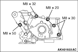
3.
| caution |
The mounting bolts are different in length. Take care not
to use wrong bolts in wrong places.
|
Install the oil pump case to the cylinder head, and tighten mounting bolts to a specified
torque of 14 ± 1 N·m.
|
|
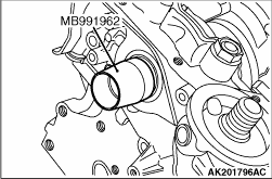
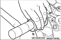
1.Place the special tool Crankshaft front oil seal guide (MB991962) on the crankshaft’s
front end and apply engine oil to the its outer circumference.
|
|
2.Apply engine oil to the oil seal lip, then push the oil seal along the guide by hand
until it touches the front case. Tap the oil seal into place using the special tool Camshaft
oil seal installer (MD998306).
|
|
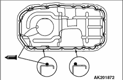
1.Completely remove existing form-in-place gasket from the cylinder block (oil pan mounting
surface) and oil pan.
2.Apply a 4 ± 1mm bead of form-in-place gasket to the oil pan at the positions
shown in the illustration.
Specified sealant:
Three bond 1207F or equivalent
3.Install the oil pan to the cylinder block and tighten the tightening bolt to the specified
torque of 7.0 ± 1.0 N·m.
|
|
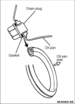
| caution |
Installing the gasket with the wrong side facing the oil
pan will result in oil leakage.
|
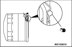
Replace the drain plug gasket with a new one. Install it with the side indicated in the
illustration toward the oil pan.
|
|
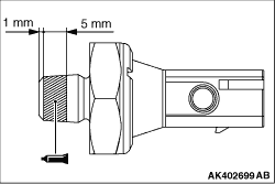
| caution |
- The threaded part tip of
the switch must be clear of the sealant.
- Be careful not to overtighten the switch.
|
1.Completely remove existing sealant from the oil pressure switch and the switch mounting
hole on the oil pump case.
2.Apply specified sealant to the threaded part of the oil pressure switch as shown.
Specified sealant:
Three bond 1207F or equivalent
3.Install the oil pressure switch to the oil pump case by tightening to a specified
torque of 10 ± 2 N·m.
|
|
1.Clean the filter mounting surface on the front case.
2.Apply engine oil to the O-ring of the oil filter.
|
|
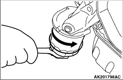
3.
| caution |
If the filter is tightened by hand only, it will be insufficiently torqued,
resulting in oil leaks.
|
Screw the oil filter in and tighten the oil filter to the specified torque using a commercially
available filter wrench from where the O-ring has come into contact with the oil filter mounting
surface.
Specified torque:
MD348631, MD365876 16 ± 4 N·m (approx. 3/4 of a turn)
MD360935 14 ± 2 N·m (approx. 1 turn)
|
)

)
)
)
)
)
)
)
)
)
)