|
|
1.Before cleaning the cylinder head, check it for traces of water and gas leakage and
for cracks and any other damage.
|
|
|
2.Thoroughly remove oils, scale, sealants, carbon and other contamination. Clean the
oil passages, then check using compressed air that they are not blocked.
|
|
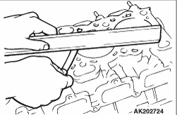
3.Check the cylinder head gasket surface for warp using a straightedge and thickness gauge.
If the surface is warped beyond the limit, grind the surface for rectification.
| caution |
The thickness of the metal that can be removed by grinding
from both the cylinder head and the mating cylinder block is limited to 0.2 mm in total.
|
Gasket surface warp
Standard value: 0.03 mm or less
Limit: 0.2 mm
Grinding limit: 0.2 mm
Cylinder head height (standard value for new part):
|
|
|
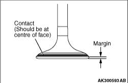
1.Check the valve face for correct contact with the seat. Reface the valve if the contact
is partial or one sided.
|
|
2.Measure the margin.
Replace the valve if its margin is smaller than the limit.
Standard values:
Intake 1.0 mm
Exhaust 1.5 mm
Limits:
Intake 0.5 mm
Exhaust 1.0 mm
|
|
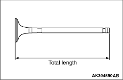
3.Measure the total length of the valve.
Replace the valve if the length is less than the limit.
Standard values:
Intake 106.35 mm
Exhaust 106.85 mm
Limits:
Intake 105.85 mm
Exhaust 106.35 mm
|
|
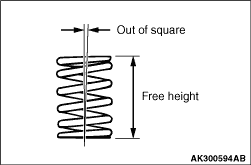
1.Measure the free height of the spring.
Replace the spring if its height is smaller than the limit.
Standard value: 54.8 mm
Limit: 53.8 mm
2.Measure the squareness of the spring.
Replace the spring if it is out of square beyond the limit.
Standard value: 2° or smaller
Limit: 4°
|
|
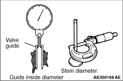
Measure the valve guide inside diameter and valve stem diameter to calculate the clearance
between the valve guide and valve stem.
If the limit is exceeded, replace the valve guide or valve, or both.
Standard values:
Intake 0.02 - 0.05 mm
Exhaust 0.03 - 0.06 mm
Limits:
Intake 0.10 mm
Exhaust 0.15 mm
|
|
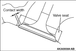
Assemble the valve, then measure the contact width. If the measurement exceeds the specified
limit, replace or correct the valve seat.
Standard value: 0.9 - 1.3 mm
| caution |
If the variation in the width exceeds 0.2 mm even if the contact width is
within the standard value, replace or correct the valve sheet.
|
|
|
|
1.Before reconditioning the valve seat, check the clearance between the valve guide
and valve stem and, if necessary, replace the valve guide.
|
|
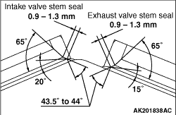
2.Resurface the valve seat to the indicated width and angles.
3.After resurfacing, lap the valve and valve seat using lapping compound.
|
|
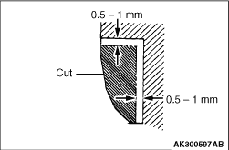
1.Cut inside of the valve seat to be replaced until its wall becomes thin enough for removal,
then remove the valve seat.
|
|
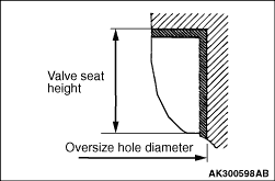
2.Rebore the valve seat hole in the cylinder head to a diameter matched to the diameter
of the selected oversize valve seat.
Intake valve seat hole diameters:
0.3 oversize 31.30 - 31.33 mm
Exhaust valve seat hole diameters:
0.3 oversize 27.80 - 27.82 mm
3.Before fitting the valve seat, cool it in liquid nitrogen to prevent damage to its
hole in the cylinder head due to interference.
4.Resurface the valve seat. See the VALVE SEAT RECONDITIONING section.
|
|
|
1.Force out the valve guide toward the cylinder block using a press.
|
|
|
2.Machine the valve guide hole in the cylinder head to the size matched to the selected
oversize valve guide.
Valve guide hole diameters
0.05 oversize: 10.55 - 10.57mm
|
|
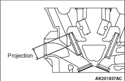
3.Press-fit the valve guide until it remains protruded above the cylinder head by the amount
indicated in the illustration.
Standard value: 22.7 - 23.3 mm
| note |
Press the valve guide from above the cylinder head.
|
| note |
The valve guides for the intake valves are different in length from those for the exhaust
valves (48 mm for intake valves; 55 mm for exhaust valves)
|
4.After installing the valve guide, insert a new valve in it to check for smooth movement.
|
)
)
)
)
)
)
)
)
)
)