|
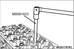
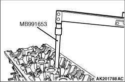
Use the special tool Cylinder head bolt wrench (MB991653) to loosen the cylinder head
bolts.
|
|
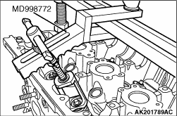
Compress the valve spring using the special tool Valve spring compressor
(MD998772), then remove the retainer lock.
| note |
Store removed valves, springs and other parts, after putting to each of them a tag that
identifies its cylinder No. or installation location.
|
|
|
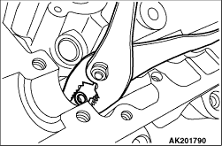
Using pliers, remove the valve stem seal.
|
|
|
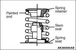
1.Install the valve spring seat.
|
|
|
3.Apply a thin coat of engine oil to a new valve stem seal.
|
|
4.
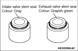
| note |
Do not confuse the stem seals for intake valves with those for exhaust valves.
|
|
|
5.
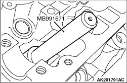
| caution |
- Do not reuse the valve stem seal.
- The special tool must always be used when installing the valve stem
seal. Improper installation could result in oil leaks past the valve guide.
|
Use the special tool Valve seal installer (MB991671) to install the stem seal on the valve
guide. Use the stem of the valve to guide the stem seal.
|
|
Install each valve spring with the painted end toward the rocker arm.
|
|
Compress the valve spring using the special tool Valve spring compressor (MD998772), then
install the retainer lock.
|
|
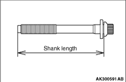
1.When reusing a cylinder head bolt, check that its nominal length (shank length) is not
greater than the limit. If the limit is exceeded, replace the bolt.
Limit: 103.2 mm
2.Apply engine oil to the threads and washer of the bolt.
|
|
3.
| note |
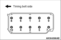
Use the special tool Cylinder head bolt wrench (MB991653) to tighten the bolts.
|
|
|
4.Tighten the bolts to 49 ± 2 N·m in the indicated sequence.
5.Loosen all the bolts completely.
6.Tighten the bolts again to a torque of 20 ± 2 N·m in the indicated
sequence.
|
|
7.
| caution |
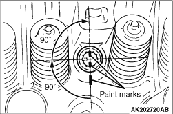
- If the tightening angle
is smaller than 90°, proper fastening performance could not be assured. Be sure to
respect that angle.
- If the bolt is tightened to an angle greater than the specified angle, loosen the
bolt completely and then retighten it beginning with the first step.
|
Make paint marks on each bolt’s head and on the cylinder head.
8.Turn the bolts 90° in the tightening direction and in the indicated sequence.
9.Give another 90° turn in the tightening direction to each bolt, making sure
that the paint mark on the bolt head and that on the cylinder head are on the same line.
|
)

)
)
)
)
)
)
)
)
)
)