|
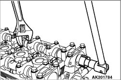
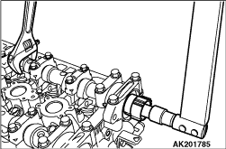
Holding the hexagonal portion of the camshaft with a wrench, remove the
cam position sensing cylinder.
|
|
|
While using care not to spill diesel fuel in the lash adjuster, install
the lash adjuster on the rocker arm.
|
|
| caution |
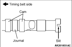
- Do not confuse intake and exhaust camshafts.
- A 4 mm slit is on the rear end of the intake camshaft.
|
Apply engine oil to the camshaft journal and cams before installation.
|
|
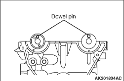
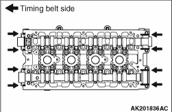
1.Place the dowel pins of the camshafts in the positions shown in the illustration.
| note |
By getting the dowel pins into position shown in the illustration, the camshaft slots
of tightening the cylinder head bolt are put in position.
|
|
|
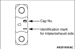
2.The bearing caps No. 2 to 5 are identical in shape. Before installation, be sure to check
the cap numbers and identification marks so that right bearing caps are installed in right places.
Identification marks (Die-stamped on front and No.
2 to 5 bearing caps)
I: Intake side
E: Exhaust side
3.Completely remove existing sealant from the bearing caps and cylinder head.
|
|
4.Apply specified sealant to the cylinder head at the points shown in the illustration.
Specified sealant:
Three bond 1212D or equivalent
5.Install the bearing caps in position and tighten bolts increasingly by giving turns
2 to 3 times each.
| note |
Completely wipe off excess of applied sealant that comes out.
|
6.Finally, tighten the bearing cap bolts to a specified torque.
Specified torque
Front bearing cap: 25 ± 1 N·m
Bearing cap: 11 ± 1 N·m
Rear right bearing cap: 25 ± 1 N·m
Rear left bearing cap: 25 ± 1 N·m
7.Check that the rocker arms are installed in position.
|
|
Holding the hexagonal portion of the camshaft, tighten the cam position
sensing cylinder to a specified torque of 22 ± 4 N·m.
|
|
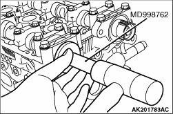
Using the special tool Circular packing installer (MD998762), install
the circular packing into the cylinder head.
|
|
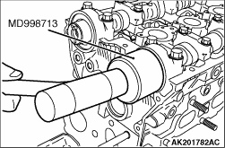
Using the special tool Oil seal installer (MD998713), install the oil
seal into the cylinder head.
|
|
|
1.
| caution |
Check the filter for foreign matters, damage and deformation
before installation.
|
|
|
|
1.Apply a small amount of engine oil to the o-ring of the oil feeder control valve.
|
|
|
2.Install the oil feeder control valve to the cylinder head.
|
|
|
3.Tighten the oil feeder control valve bolt to the specified torque of 11 ± 1
N·m.
|
)

)
)
)
)
)
)
)
)