|
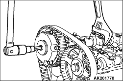
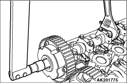
Remove the plug cap using a wrench fitted on the hexagonal portion of
the camshaft.
|
|
|
1.By turning the crankshaft, position the No.1 cylinder at the Top Dead Center of the
compression stroke.
|
|
2.If the timing belt is to be reused, it is necessary to install it in the same direction
as it was before. Mark an arrow that shows the direction of rotation on the back surface of
the timing belt with chalk, etc.
|
|
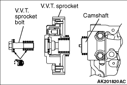
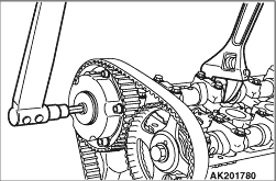
Remove the V.V.T. sprocket bolt using a wrench fitted on the hexagonal
portion of the camshaft.
|
|
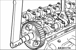
Remove the camshaft sprocket bolt using a wrench fitted on the hexagonal
portion of the camshaft.
|
|
Tighten the camshaft sprocket bolt to 88 ± 10 N·m while preventing
the camshaft from rotation using a wrench fitted on the hexagonal portion of the camshaft.
|
|
1.Apply a proper minimum quantity of engine oil to the following points.
- Camshaft end
- Insertion hole in V.V.T. sprocket (all over inside and outside surfaces)
- Threads and head of V.V.T. sprocket bolt
- Bearing surface of V.V.T. sprocket bolt
2.Install the V.V.T. sprocket onto the camshaft.
3.Make sure that the V.V.T. sprocket is installed all the way onto the camshaft. Holding
the hexagonal portion of the camshaft with a wrench, check that the V.V.T. sprocket does not
turn.
|
|
4.Holding the hexagonal portion of the camshaft with a wrench, tighten
the V.V.T. sprocket bolt to a specified torque of 55 ± 5 N·m.
5.Holding the hexagonal portion of the camshaft with a wrench, check that the V.V.T.
sprocket is not loose to turn.
| note |
This check is to ascertain that the V.V.T. sprocket is locked at the most retarding position
by means of internal pin.
|
|
|
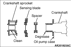
1.Clean the hole in the crankshaft sprocket.
2.Clean and degrease the mating surfaces of the crankshaft sprocket and spacer; sensing
blade; crankshaft sprocket; and oil pump case.
| note |
Degreasing is necessary to prevent decrease in friction between the mating surfaces due
to presence of oil.
|
|
|
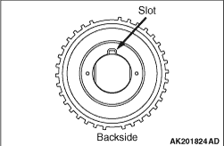
3.Assemble the crankshaft sprocket and sensing blade, projection to slot, as shown.
|
|
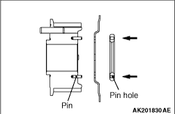
4.Align the pins to the pin holes and apply even pressure in the arrow direction.
5.
| caution |
When installing the sprocket, do not bend the sensing blade.
|
Install the crankshaft sprocket onto the crankshaft.
|
|
1.If the auto-tensioner rod remains in its fully extended position, reset it to the retracted
position as follows:
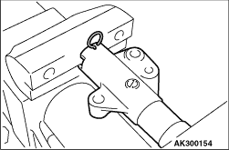
(1)
Clamp the auto-tensioner in a vise at right angles to the jaws.
(2)
|
|
| caution |
Because the leak down of the auto-tensioner takes a long time,
slowly insert the rod. If the rod is suddenly inserted, the auto-tensioner could be damaged.
|
|
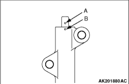
Push in the rod little by little with the vise until the set hole A in the rod is aligned
with the set hole B in the cylinder.
(3)
Insert a piece of wire (1.4 mm diameter) into the set holes.
(4)
Remove the auto-tensioner from the vise.
2.Install the auto-tensioner in position. Leave the wire installed until the auto-tensioner
is completely installed.
|
|
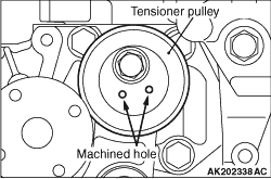
Install the tensioner pulley onto the tensioner arm, with the machined holes facing in
front as shown.
|
|
|
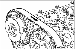
1.For aligning the timing marks on the camshaft sprocket and V.V.T. sprocket, install
the rocker cover temporarily.
|
|
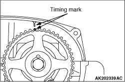
2.Align the timing mark on the camshaft sprocket.
|
|
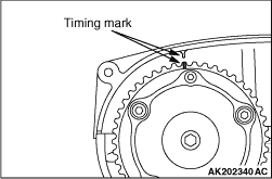
3.Align the timing mark on the V.V.T. sprocket.
|
|
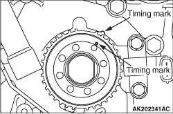
4.Align the timing mark on the crankshaft sprocket.
5.First fit the timing belt onto the crankshaft sprocket.
6.Fit the timing belt onto the idler pulley.
|
|
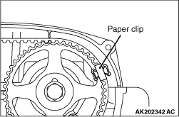
7.Fit the timing belt onto the camshaft sprocket, and bind it with paper clip in the illustrated
shown in the illustration.
|
|
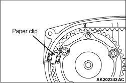
8.Fit the timing belt onto the V.V.T. sprocket, and bind it with paper clip in the position
shown in the illustration.
|
|
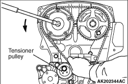
9.Fit the timing belt onto the tensioner pulley.
| note |
To make belt installation easier, turn the V.V.T. sprocket a little counter-clockwise.
|
|
|
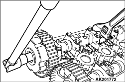
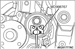
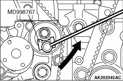
10.Using the special tool of tensioner pulley socket (MD998767), apply the tension to the
timing belt by turning the tensioner pulley counterclockwise, then temporally tighten the fixing
bolt of the tensioner pulley and fix the tensioner pulley firmly.
11.Turn the crankshaft a quarter turn counter-clockwise, then turn it clockwise to align
the timing marks.
|
|
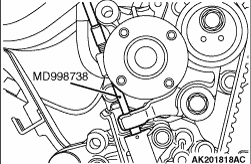
12.Install the special tool Set screw (MD998738) in position and drive it in to such an extent
that the wire inserted when the auto tensioner was installed lightly moves.
|
|
13.
| caution |
The timing belt is loosened with the rotation of the intake and exhaust
camshafts. Take care that the timing belt does not slip out of place.
|
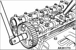
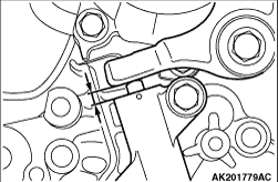
Loosen the lock bolt holding the tensioner pulley.
14.Turn the torque wrench attached to the special tool Tensioner pulley socket (MD998767)
counter-clockwise until the slack in the timing belt is taken up.
15.Torque to 0.8 N·m with the torque wrench.
16.Check that all the timing marks are in alignment.
17.Remove the special tool Set screw (MD998738) installed at step 12.
18.Give the crankshaft two turns clockwise, and leave it in that state for approximately
15 minutes.
|
|
19.Check to see if the wire inserted when the auto tensioner was installed can be easily
pulled out. If so, the belt tension is optimal and the wire may be removed. Alternatively, if
the protrusion of the auto tensioner rod is within the specified range of standard values, the
belt tension is optimal.
Standard value: 4.8 - 5.5 mm
20.
| caution |
When the crankshaft bolt was turned counter-clockwise, be sure to check
its tightening torque. If the bolt is loose, retighten it.
|
If the wire cannot be easily removed, repeat the steps from 12 to 18 above for proper
tension of the belt.
21. Finally, remove the temporarily installed rocker cover.
|
|
|
1.
| caution |
Do not reuse washer.
|
Replace washer on the plug cap.
|
|
2.Holding the hexagonal portion of the camshaft with a wrench, tighten
the plug cap to a specified torque of 21 ± 3 N·m.
|
|
|
1.Completely remove existing form-in-place gasket from the rocker cover and cylinder
head.
|
|
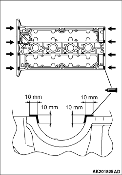
2.Apply beads of FIPG on the surfaces of the rocker cover indicated in the illustration.
Specified sealant:
Three bond 1212D or equivalent
|
|
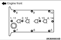
3.Install the rocker cover to the cylinder head before the FIPG hardens, and tighten the
each bolt to 5.0 ± 1.0 N·m in the order (1-14) shown.
4.After tightening of step 3, tighten the each bolt to 7.0 ± 1.0 N·m
in the order (1-10) shown.
|
)

)
)
)
)
)
)
)
)
)
)
)
)
)
)
)
)
)
)
)
)
)
)
)
)
)
)