|
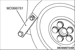
1.Lock the flywheel using the special tool Flywheel stopper (MD998781).
2.Then loosen the crankshaft bolts.
|
|
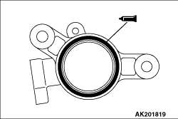
1.Completely remove existing form-in-place gasket from the cam position sensor support and
cylinder head (surface to which cam position sensor support is fitted).
2.Apply a 3 ± 1 mm bead of form-in-place gasket (FIPG) to the area shown.
Specified sealant:
Three bond 1207F or equivalent
3.With the tightening bolt, tighten the cam position sensor support and the air intake
pipe bracket assembly together with the cylinder head to the specified torque of 14 ± 1
N·m.
|
|
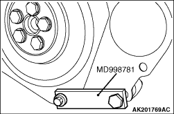
1.Lock the drive plate using the special tool Flywheel stopper (MD998781).
|
|
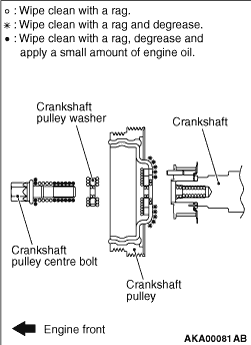
2.Wipe off the dirt on the crankshaft and the crankshaft pulley as shown in the figure using
a rag.
3.Wipe off the dirt on the crankshaft pulley as shown in the figure using a rag, and
then degrease the areas.
| note |
Degrease them to prevent drop in the friction coefficient of the pressed area which is
caused by oil adhesion.
|
4.Install the crankshaft pulley.
5.Apply an adequate and minimum amount of engine oil to the thread
of the crankshaft pulley centre bolt and the lower area of the flange.
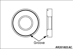
6.Wipe off the dirt on the crankshaft pulley washer as shown in the figure using a rag.
|
|
7.Install the washer, whose grooved surface is toward the bolt flange.
8.Tighten the crankshaft bolt to the specified torque of 181 N·m.
|
)

)
)
)
)
)