Pre-removal Operation
- Air Cleaner and Air Intake Hose Removal (Refer to GROUP
15, Air Cleaner
 ). ).
- Engine Coolant Draining (Refer to GROUP 14, On-vehicle Service - Engine
Coolant Replacement ).
- Engine Oil Draining (Refer to GROUP 12, On-vehicle Service - Engine Oil
Replacement ).
- Washer Tank Removal (Refer to GROUP 51, Windshield Washer ).
- Crankshaft Pulley Removal (Refer to ).
- Alternator Assembly Removal (Refer to GROUP 16, Alternator Assembly ).
- Water Pump Pulley Removal (Refer to GROUP 14,Water Pump ).
- Cylinder Head Cover Removal (Refer to ).
|
Post-installation Operation
- Cylinder Head Cover Installation (Refer to ).
- Water Pump Pulley Installation (Refer to GROUP 14, Water Pump ).
- Alternator Assembly Installation (Refer to GROUP 16, Alternator Assembly ).
- Crankshaft Pulley Installation (Refer to ).
- Washer Tank Installation (Refer to GROUP 51, Windshield Washer ).
- Engine Oil Refilling (Refer to GROUP 12, On-vehicle Service - Engine Oil
Replacement ).
- Engine Coolant Refilling (Refer to GROUP 14, On-vehicle Service - Engine
Coolant Replacement ).
- Air Cleaner and Air Intake Hose Installation (Refer to GROUP 15, Air Cleaner ).
- Drive Belt Tension Check and Adjustment (Refer to ).
|
|
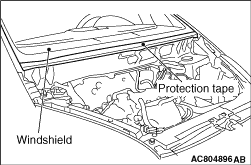
After removing the cowl top panel, attach a protection tape for the windshield on the
lower area of the windshield.
|
|
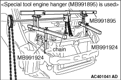
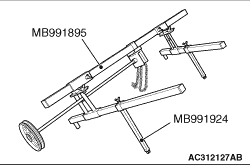
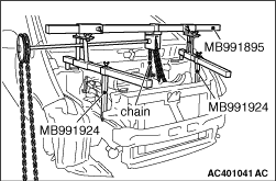
1.<Special tool engine hanger (MB991895) is used>
(1)
Remove the foot from the front side of special tool engine hanger (MB991895),
and install special tool engine hanger attachment (MB991924) instead.
(2)
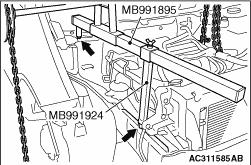
Set the rear-side foot of special tool (MB991895) to the front strut mounting nut.
(3)
Set special tool (MB991924) to the welding area of the front side member.
(4)
Install the chain of special tool (MB991895) to the engine assembly to hold the engine
and transmission assembly.
|
|
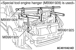
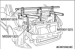
2.<Special tool engine hanger (MB991928) is used>
(1)
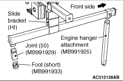
Assemble special tool engine hanger (MB991928). Set following parts to
the base hanger.
- Slide bracket (HI)
- Engine hanger attachment (MB991925) <Front side>
- Foot (short) (MB991933) <Rear side>
- Joint (50) (MB991929) <Rear side>
(2)
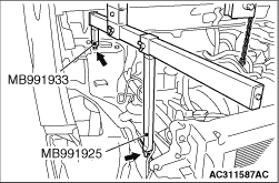
Set special tool (MB991933) to the front strut mounting nut.
(3)
Set special tool (MB991925) to the welding area of the front side member.
(4)
Connect the chain to the engine hanger plate to hold the engine and transmission assembly.
|

|
1.Set special tool crankshaft adapter (MB992000) to the crankshaft, and install the crankshaft
pulley bolt and washer.
|
|
2.
| caution |
Never turn the crankshaft anti-clockwise.
|
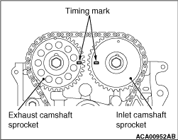
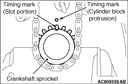
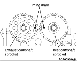
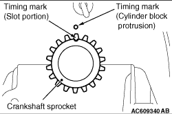
Turn the crankshaft clockwise, and align the timing marks of the camshaft sprocket (2
conceive areas in front of the camshaft sprocket) and the crankshaft sprocket. Then set No.1
cylinder to the TDC.
|
|
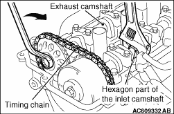
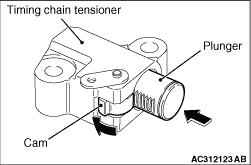
3.While holding the inlet camshaft hexagonal area with a wrench or a similar tool, slightly
turn the exhaust camshaft clockwise to tighten the timing chain at the timing chain tensioner
side and shorten the plunger of the timing chain tensioner.
|
|
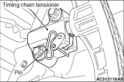
4.With the plunger of the tensioner shortened, insert a pin (3 mm or less in diameter) or
a similar tool to the hole shown in the illustration of the timing chain tensioner.
5.
| caution |
Do not turn the crankshaft after removing the timing
chain tensioner.
|
Remove the timing chain tensioner.
|
|
1.Set special tool crankshaft adapter (MB992000) to the crankshaft, and install the crankshaft
pulley bolt and washer.
|
|
2.Turn the crankshaft clockwise, and align the timing marks of the camshaft sprocket (2
conceive areas in front of the camshaft sprocket) and the crankshaft sprocket. Then set No.1
cylinder to the TDC.
|
|
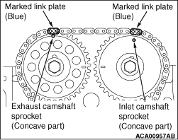
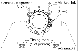
3.Locate the marked link plate (blue-coloured area) of the timing chain as shown in the
illustration of each sprocket, and install the timing chain.
|
|
4.Install the timing chain guide, the tensioner lever assembly, and the timing chain tensioner.
| note |
When the plunger of the timing chain tensioner is stretched, remove the pin or the similar
tool. While pressing the cam in the lower area of the timing chain tensioner, press and shorten
the plunger to keep the status with the pin or the similar tool.
|
5.After installing the timing chain tensioner, confirm that the timing marks of each
sprocket are aligned with the TDC of No.1 cylinder, and the marked link plate (blue-coloured
area) of the timing chain is aligned with the specified position of each sprocket. Then pull
out the pin or a similar tool of the timing chain tensioner, and apply tension to the timing
chain.
6.Remove special tool (MB992000).
|
|
|
1.Remove the sealant from the installation face of the timing chain tensioner cover
and the timing chain case assembly.
|
|
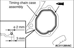
2.Apply a bead of the specified sealant to the mating surface of the timing chain case assembly.
Specified sealant: ThreeBond 1217G or equivalent
| note |
Install the timing chain case cover immediately after applying sealant.
|
|
|
|
1.Remove the sealant from the timing chain case assembly and the installation face of
the timing chain case assembly on the cylinder block and the cylinder head.
|
|
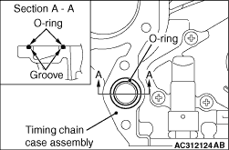
2.Securely fit the O-ring in the groove of timing chain case assembly without causing any
torsion and damage.
3.
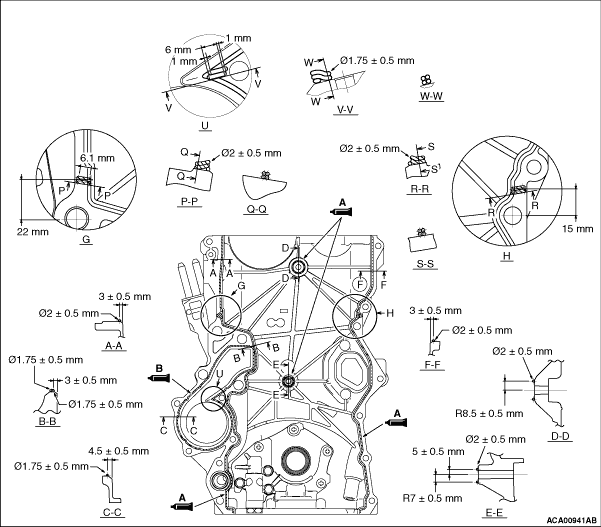
Apply a bead of the sealant to the cylinder block and cylinder head mating surface of
the timing chain case assembly as shown.
Specified sealant:
A: ThreeBond 1217G or equivalent
B: ThreeBond 1217D or equivalent
4.
| caution |
After the installation, until a sufficient period of
time (one hour or more) elapses, do not apply the oil or water to the sealant application area
or start the engine.
|
Install the timing chain case assembly to the cylinder block and cylinder head so that
the sealant does not contact other parts.
| note |
Install the timing chain case assembly immediately after applying sealant.
|
|
|
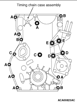
5.Install the timing chain case assembly mounting bolts to the position shown, and tighten
the bolts to the specified torque.
|
|
Bolt (symbol)
|
Diameter × length mm
|
Tightening torque N·m
|
A
|
6 × 25
|
9.5 ± 2.5
|
B
|
6 × 30
|
9.5 ± 2.5
|
C
|
6 × 45
|
9.5 ± 2.5
|
D
|
10 × 50
|
42 ± 16
|
E
|
10 × 90
|
42 ± 16
|
|
|
|
|
1.Carefully remove the drying material and other foreign materials on the installation
groove for the water pump O-ring.
|
|
|
2.Carefully remove the drying material and other foreign materials on the water pump
installation area of the timing chain case assembly.
|
|
|
3.Sufficiently apply water or coolant to the O-ring to prevent it from dropping using
brushes.
|
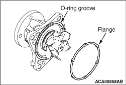
|
4.Securely fit the O-ring flange area into the installation groove of the water pump O-ring.
5.Reverse the water pump carefully and check that the O-ring does not fall down.
6.
| caution |
When installing the water pump, pay attention not to let the O-ring fall
down or be bitten. Otherwise, a coolant leak may be caused.
|
Install the water pump to the timing chain case assembly.
| note |
The water pump assembly mounting bolts are also used for the timing chain case assembly.
Thus install the water pump assembly together with the timing chain case assembly, or else immediately
after installing the timing chain case assembly.
|
|
|
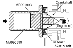
1.Apply a small amount of engine oil to the outer circumference of special tool crankshaft
front oil seal guide (MB991993) and install it to the crankshaft.
2.Apply a small amount of engine oil to the entire inner circumference of the oil seal
lip.
3.
| caution |
Install the crankshaft front oil seal not to damage the crankshaft
front oil seal.
|
Using special tool differential oil seal installer (MB990699), drive the oil seal so that
it is flush with the timing chain case assembly.
|
)
)
)
)
)
)
)
)
)
)
)
)
)
)
)
)
)
)
)
)
)
)
)
)
)
)