|
1.
| caution |
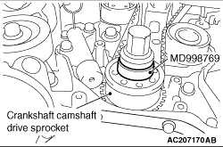
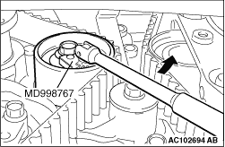
Be sure to use special tool crankshaft sprocket spacer (MD998769) when installing the crankshaft pulley centre bolt to the crankshaft. If the bolt is installed directly to the crankshaft, the tip of the bolt and the thread of the crankshaft may be damaged.
|
Set the special tool, the crankshaft pulley washer and the crankshaft pulley centre bolt to the crankshaft camshaft drive sprocket.
|
|
2.
| caution |
Never turn the crankshaft anti-clockwise.
|
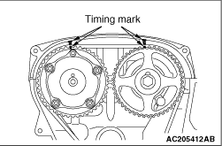
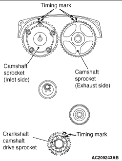
Turn the crankshaft clockwise, align each timing mark to set No.1 cylinder to TDC of its compression stroke.
|
|
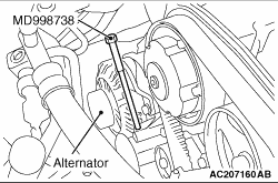
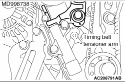
3.Remove the timing belt under cover rubber plug and then set special tool adjusting bolt (MD998738).
|
|
4.Screw in the special tool with hands until it contacts the timing belt tensioner arm.
|
|
5.
| caution |
The special tool can be gradually installed at a rate of a 30 degree turn per second. If it is screwed in all at once, the timing belt tensioner adjuster rod will not easily retract and the special tool may bend.
|
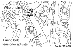
Gradually screw in the special tool. Then align the timing belt tensioner adjuster rod set hole with the timing belt tensioner adjustor cylinder set hole, and insert a wire or a pin.
6.
| caution |
To reuse the valve timing belt, draw an arrow indicating the rotating direction (clockwise) on the back of the belt using chalk, etc.
|
After removal of the special tool, loosen the timing belt tensioner pulley mounting bolts and remove the valve timing belt.
|
|
1.Set according to the following procedures when the timing belt tensioner adjuster rod is fully extended.
(1)
|
|
| caution |
If the compression is too fast the procedure may damage the rod. Make a point to slowly and thoroughly compress.
|
|
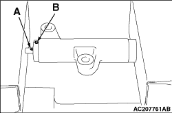
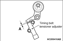
Slowly compress the timing belt tensioner adjuster rod using a press or vice, then align the set hole A of the rod with set hole B of the timing belt tensioner adjuster cylinder.
(2)
Insert a wire or pin in the set hole aligned.
|
|
| note |
When replacing the timing belt tensioner adjuster with new parts, the timing belt tensioner adjuster is set with a pin.
|
|
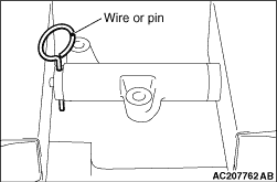
2.Install the timing belt tensioner adjuster to the engine and then tighten the mounting bolts to the specified torque. Do not remove the wire or pin until the tension of the valve timing belt is adjusted.
Tightening torque: 23 ± 3 N·m
|
|
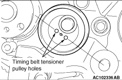
Temporarily tighten the timing belt tensioner pulley as shown.
|
|
1.
| caution |
Be sure to use special tool crankshaft sprocket spacer (MD998769) when installing the crankshaft pulley centre bolt to the crankshaft. If the bolt is installed directly to the crankshaft, the tip of the bolt and the thread of the crankshaft may be damaged.
|
Set the special tool, the crankshaft pulley washer and the crankshaft pulley centre bolt to the crankshaft camshaft drive sprocket.
|
|
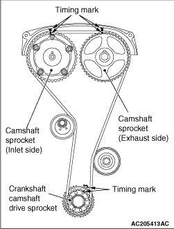
2.Align the timing marks on the camshaft sprocket and crankshaft camshaft drive sprocket.
|
|
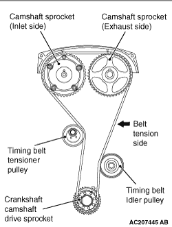
3.Incorporate the valve timing belt in the following manner so that the tensile force of the belt is not lax.
(1)
Pass the valve timing belt around the crankshaft camshaft drive sprocket and the timing belt idler pulley in that order.
(2)
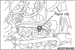
Pass the valve timing belt around the camshaft sprocket (exhaust side), and fix it with a paper clip as shown.
(3)
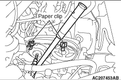
Pass the valve timing belt around the camshaft sprocket (inlet side) while aligning the timing marks on the rocker cover and the camshaft sprocket with a wrench. Then, fix the belt with paper clips as shown.
(4)
Pass the valve timing belt around the timing belt tensioner pulley.
(5)
|
|
| caution |
Incorporate the valve timing belt. Then apply reverse rotation (anti-clockwise rotation) pressure to the camshaft sprocket. Re-check to see that each timing mark is aligned while the tension side of the belt is right.
|
|
Remove the two paper clips.
|
|
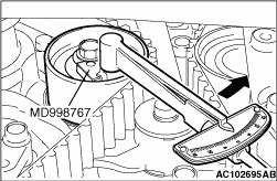
4.Using special tool tensioner wrench (MD998767), turn the timing belt tensioner pulley in the direction shown to apply tension to the valve timing belt. Then tighten the timing belt tensioner pulley mounting bolts temporarily to fix the timing belt tensioner pulley.
|
|
5.Check that the timing marks are aligned.
6.Adjust the valve timing belt tension.
|
|
1.Set special tool adjusting bolt (MD998738) used when removing the valve timing belt.
2.
| caution |
Always screw in the special tool in with your hands, since use of a spanner or other tools may damage the wire or pin inserted in the timing belt tensioner adjuster.
|
Gradually screw in the special tool to a position in which the wire or pin inserted in the timing belt tensioner adjuster lightly moves.
3.Turn the crankshaft 1/4 of a revolution in the anti-clockwise direction.
|
|
4.Turn the crankshaft in the clockwise direction, align each timing mark to set No.1 cylinder to TDC of its compression stroke.
5.Loosen the timing belt tensioner pulley mounting bolt.
|
|
6.
| caution |
When tightening the mounting bolt, ensure that the timing belt tensioner pulley does not rotate with the bolt. Allowing it to rotate with the bolt can cause deficient tension of the belt.
|
With special tool tensioner wrench (MD998767) and torque wrench, apply tension torque 0.8 N·m to the valve timing belt, and tighten the timing belt tensioner pulley mounting bolt to the specified torque.
Tightening torque: 48 ± 6 N·m
|
|
7.Remove wire or pin inserted to timing belt tensioner adjuster.
|
|
8.Remove the special tool adjusting bolt (MD998738), and install the rubber plug to the timing belt under cover.
9.Rotate crankshaft clockwise two turns, and leave it for about 15 minutes.
|
|
10.Insert wire or pin removed in step 7 again, and ensure that it can be pulled out with a light load. When wire or pin can be lightly removed, appropriate tension is applied on timing belt. In this case, remove wire or pin. Also the projection of timing belt tensioner adjuster rod (A) is within the standard value, appropriate tension is applied.
Standard value (A): 4.8 - 5.5 mm
11.If wire or pin cannot be easily pulled out, repeat Step 1 through Step 9 to reach proper valve timing belt tension.
|
|
12.Check that the timing marks are aligned.
|
|
13.Remove special tool crankshaft sprocket spacer (MD998769), the crankshaft pulley washer and the crankshaft pulley centre bolt.
|
 ).
).)
)
)
)
)
)
)
)
)
)
)
)
)
)
)
)
)