Pre-removal Operation
- Fuel Line Pressure Reduction [Refer to GROUP
13C, On-vehicle Service - Fuel Pump Connector Disconnection (How to Reduce Pressurized
Fuel Lines)
 ]. ].
- Engine Coolant Draining (Refer to GROUP 14, On-vehicle Service - Engine
Coolant Replacement ).
- Engine Oil Draining (Refer to GROUP 12, On-vehicle Service - Engine Oil
Replacement ).
- Inlet Manifold Removal (Refer to GROUP 15, Inlet Manifold ).
- Water Pump Inlet Pipe Removal (Refer to GROUP 14, Water Hose and Water Pipe ).
- Ignition Coil Removal (Refer to GROUP 16, Ignition System - Ignition Coil ).
- Valve Timing Belt Removal (Refer to ).
- Rocker Cover Assembly Removal (Refer to ).
|
Post-installation Operation
- Rocker Cover Assembly Installation (Refer to ).
- Valve Timing Belt Installation (Refer to ).
- Ignition Coil Installation (Refer to GROUP 16, Ignition System - Ignition
Coil ).
- Water Pump Inlet Pipe Installation (Refer to GROUP 14, Water Hose and Water Pipe ).
- Inlet Manifold Installation (Refer to GROUP 15, Inlet Manifold ).
- Engine Oil Refilling (Refer to GROUP 12, On-vehicle Service - Engine Oil
Replacement ).
- Engine Coolant Refilling (Refer to GROUP 14, On-vehicle Service - Engine
Coolant Replacement ).
- Fuel Leak Check
|
|
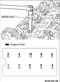
Use special tool cylinder head bolt wrench (MB991653) to loosen the cylinder head bolts
in two or three steps in the order of the numbers shown in the illustration.
| note |
If the cylinder head bolts cannot be pulled out due to the washer being trapped in the
valve spring, raise the bolt slightly, then remove it while holding it by using a magnet.
|
|
|
|
1.
| caution |
Do not allow any foreign materials get into the coolant passages, oil
passages and cylinder.
|
Degrease the cylinder head gasket mounting surface.
|
|
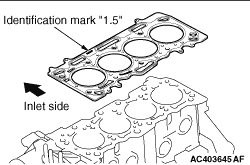
2.Assemble to the cylinder block so the cylinder head gasket identification mark of "1.5"
is at the top surface and on the inlet side.
|
|
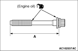
1.Check that the nominal length of each cylinder head bolt meets the limit. If it exceeds
the limit, replace the bolts with a new one.
Limit (A): 103.2 mm
2.Apply a small amount of engine oil to the thread of the bolts and to the washers.
|
|
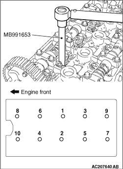
3.Use special tool cylinder head bolt wrench (MB991653) to tighten the cylinder head bolts
in the following procedures.
(1)
Tighten the bolts to 49 ± 2 N·m in the order shown.
(2)
Loosen the bolts fully in the reverse sequence to that shown.
(3)
Tighten the bolts to 20 ± 2 N·m in the order shown.
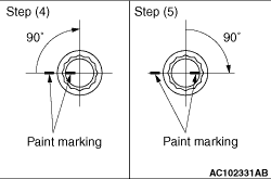
(4)
Apply a paint mark to the heads of the cylinder head bolts and cylinder head, then tighten
90° as shown.
(5)
|
|
| caution |
- When the tightening angle is smaller than
the specified tightening angle, the appropriate tightening capacity cannot be secured.
- When the tightening angle is larger than the specified tightening angle, remove
the bolt to start from the beginning again according to the procedure.
|
|
Tighten in a 90° as shown in the instructions of the figure, then check to see
that the paint mark on the head of the cylinder head bolts and the paint mark on the cylinder head
is on a linear line.
|
)
)
)
)
)
)