Pre-removal Operation
- Fuel Line Pressure Reduction [Refer to GROUP
13A, On-vehicle Service - Fuel Pump Connector Disconnection (How to Reduce Pressurized
Fuel Lines)
 ]. ].
- Engine Oil Draining (Refer to GROUP 12, On-vehicle Service - Engine Oil
Replacement ).
- Engine Coolant Draining (Refer to GROUP 14, On-vehicle Service - Engine
Coolant Replacement ).
- Air Cleaner and Air Intake Hose Removal (Refer to GROUP 15, Air Cleaner ).
- Battery and Battery Tray Removal (Refer to GROUP 54A, Battery ).
- Exhaust Manifold Assembly Removal (Refer to GROUP 15, Exhaust Manifold ).
- Timing Chain Removal (Refer to ).
|
Post-installation Operation
- Timing Chain Installation (Refer to ).
- Exhaust Manifold Assembly Installation (Refer to GROUP 15, Exhaust Manifold ).
- Battery and Battery Tray Installation (Refer to GROUP 54A, Battery ).
- Air Cleaner and Air Intake Hose Installation (Refer to GROUP 15, Air Cleaner ).
- Engine Coolant Refilling (Refer to GROUP 14, On-vehicle Service - Engine
Coolant Replacement ).
- Engine Oil Refilling (Refer to GROUP 12, On-vehicle Service - Engine Oil
Replacement ).
- Drive Belt Tension Check and Adjustment (Refer to ).
- Fuel Leak Check.
|
|
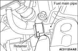
Raise the retainer, and pull out the fuel main pipe.
| note |
If the retainer comes off, install it securely after pulling out the fuel main pipe.
|
|

|
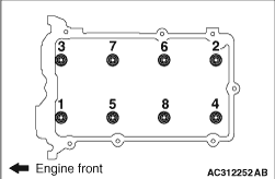
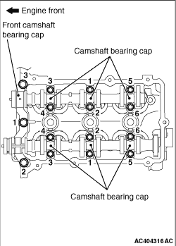
Loosen the front camshaft bearing cap mounting bolts in the order shown, and then loosen
each camshaft bearing cap mounting bolts as well. Remove the front camshaft bearing cap and
each camshaft bearing cap.
|
|
|
1.Install the engine oil pan removed together with the timing chain temporarily to the
cylinder block.
|
|
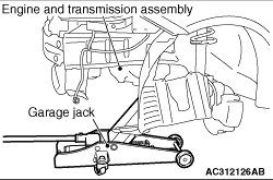
2.Place a garage jack against the temporarily-installed engine oil pan to support the engine
and transmission assembly.
|
|
3.Remove the special tools for supporting the engine and transmission assembly which were
installed when removing the timing chain.
|
|
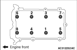
4.Loosen the cylinder head bolts in two or three steps in the order of the numbers shown
in the illustration.
|
|
|
Remove the gasket from the cylinder head and cylinder block.
|
|
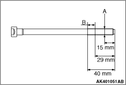
1.Inspect all reused cylinder head bolts according to the following procedure.
(1)
Measure the outside diameter shown in the illustration (arrow "A").
(2)
Measure the smaller outside diameter shown in the illustration (arrow "B").
(3)
When the difference between the outside diameters (arrow "A" and "B") exceeds the
standard value, replace the cylinder head bolt.
Standard value: 0 - 0.15 mm
2.Install the cylinder head bolts and washers onto the cylinder head.
|
|
3.Tighten the cylinder head bolts in the correct sequence to 25 ± 1 N·m.
|
|
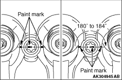
4.Put paint marks on the bolt heads and the cylinder head as illustrated.
5.
| caution |
- If the cylinder head
bolt is tightened less than the specified lower limit of 180°, the bolt may become loose.
Be sure to tighten correctly.
- If the cylinder head bolts are tightened in excess of the specified upper limit
of 184°, loosen the cylinder head bolts completely and repeat the entire procedures.
|
Tighten the cylinder head bolts in the correct sequence by 180 to 184°. Ensure
that the paint marks on the bolt heads and the cylinder are aligned in a straight line.
|
|
6.Install the special tools for supporting the engine and transmission assembly used
to remove the timing chain.
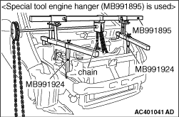
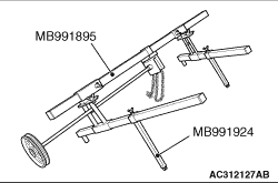
(1)
<Special tool engine hanger (MB991895) is used>
.....1.
Remove the foot from the front side of special tool engine hanger (MB991895),
and install special tool engine hanger attachment (MB991924) instead.
.....2.
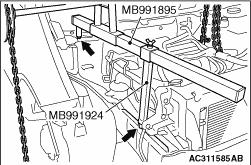
Set the rear-side foot of special tool (MB991895) to the front strut mounting nut.
.....3.
Set special tool (MB991924) to the welding area of the front side member.
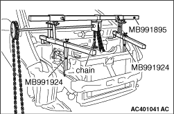
.....4.
Install the chain of special tool (MB991895) to the engine assembly to hold the engine
and transmission assembly.
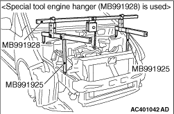
(2)
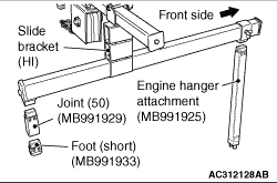
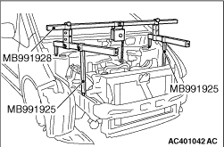
<Special tool engine hanger (MB991928) is used>
.....1.
Assemble special tool engine hanger (MB991928). Set following parts to
the base hanger.
- Slide bracket (HI)
- Engine hanger attachment (MB991925) <Front side>
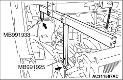
- Foot (short) (MB991933) <Rear side>
- Joint (50) (MB991929) <Rear side>
.....2.
Set special tool (MB991933) to the front strut mounting nut.
.....3.
Set special tool (MB991925) to the welding area of the front side member.
.....4.
Connect the chain to the engine hanger plate to hold the engine and transmission assembly.
7.Remove the garage jack and the temporarily-installed engine oil pan.
|
|
Tighten each camshaft bearing cap mounting bolts to the specified torque in the order
shown, and then tighten the front camshaft bearing cap mounting bolts as well.
Tightening torque:
11 ± 1 N·m (Camshaft bearing cap
mounting bolts)
20 ± 1 N·m (Front camshaft bearing cap mounting bolts)
|
|
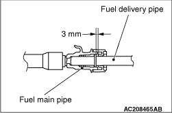
| caution |
After connecting the fuel main pipe, check that it has been securely installed by slightly
pulling in the removal direction. At this time, also check that there is approximately 3-mm
play.
|
|
)
)
)
)
)
)
)
)
)
)
)
)
)
)
)
)
)
)
)