|
|
1.Remove all ignition coils.
|
|
|
2.Remove the cylinder head cover (Refer to Camshaft Removal and Installation  <134>, <3A9>). <134>, <3A9>).
| caution |
Turn the crankshaft always clockwise.
|
|
|
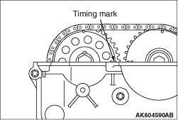
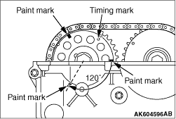
3.Turn the crankshaft clockwise, and align the timing mark on the exhaust camshaft sprocket
against the upper face of the cylinder head as shown in Figure. Therefore No.1 cylinder goes
to the compression top dead centre.
|
|
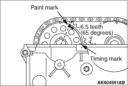
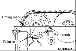
4.Apply the paint mark to the 6.5th tooth (65 degrees) anti-clockwise from the timing mark
on the exhaust camshaft sprocket.
|
|
5.Turn the crankshaft clockwise 130 degrees, and align the paint mark against the upper
face of the cylinder head as shown in Figure.
|
|
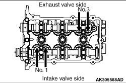
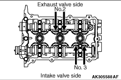
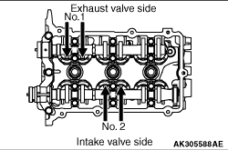
6.Using a thickness gauge, measure the valve clearance with the arrow shown in Figure. If
deviated from the standard value, make note for the valve clearance.
Standard value:
Intake valve 0.22 ± 0.04 mm
Exhaust valve 0.30 ± 0.04 mm
|
|
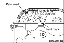
7.Apply the paint mark to the 12th tooth (120 degrees) anti-clockwise from the paint mark.
|
|
8.Turn the crankshaft clockwise 240 degrees, and align the paint mark against the upper
face of the cylinder head as shown in Figure.
|
|
9.Using a thickness gauge, measure the valve clearance with the arrow shown in Figure. If
deviated from the standard value, make note for the valve clearance.
Standard value:
Intake valve 0.22 ± 0.04 mm
Exhaust valve 0.30 ± 0.04 mm
|
|
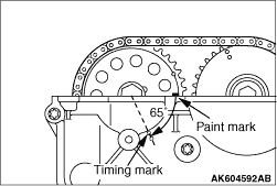
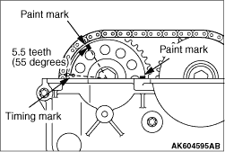
10.Apply the paint mark to the 5.5th tooth (55 degrees) clockwise from the timing mark on
the exhaust camshaft sprocket.
|
|
11.Turn the crankshaft clockwise 240 degrees, and align the paint mark against the upper
face of the cylinder head as shown in Figure.
|
|
12.Check the valve clearance with the arrow shown in Figure. If deviated from the standard
value, make note for the valve clearance.
13.If the valve clearance is deviated from the standard value, remove the camshaft and
the valve tappet. For the camshaft removal, refer to Camshaft Removal and Installation <134>, <3A9>.
|
|
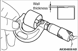
14.Using a micrometer, measure the thickness of the removed valve tappet.
|
|
15.Calculate the thickness of the newly installed valve tappet through the following
equation.
A: thickness of newly installed valve tappet
B: thickness of removed valve tappet
C: measured valve clearance
Equation
Intake valve: A = B + (C - 0.22
mm)
Exhaust valve: A = B + (C - 0.30 mm)
| note |
<134>
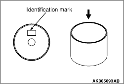
The valve tappet ranges 2.70 - 3.30 mm and has 31 types per 0.02 mm. The
thickness below a decimal point is stamped on the reverse side of the valve tappet.
Example: In case of 2.90 mm, "90" is stamped.
<3A9>
The valve tappet ranges 5.10 - 5.70 mm and has 31 types per 0.02 mm. The
thickness below a decimal point is stamped on the reverse side of the valve tappet.
Example: In case of 5.40 mm, "40" is stamped.
|
16.Install the valve tappet selected through the procedure 15, and put the camshaft in
position. For the camshaft installation, refer to Camshaft Removal and Installation <134>, <3A9>.
17.Install the cylinder head cover (Refer to Camshaft Removal and Installation <134>, <3A9>).
18.Install the ignition coils.
|
)
)
)
)
)
)
)
)
)
)
)
)