The Powertrain Control Module (PCM) monitors the signals of input and
output sensors, some all the time and others at certain times and
processes each signal. When the PCM notices that an irregularity has
continued for a specified time or longer from when the irregular signal
was initially monitored, the PCM judges that a malfunction has occurred
and will memorize the malfunction code. The code is then stored in the
memory of the PCM and is accessible through the data link (diagnostic
connector) with the use of an electronic scan tool or a voltmeter.
CHECK ENGINE/MALFUNCTION INDICATOR LIGHT
Among the on-board diagnostic items, a check engine/malfunction
indicator light comes on to notify the driver of a emission control
component irregularity.lf the irregularity detected returns to normal
or the PCM judges that the component has returned to normal, the check
engine/malfunction indicator light will be turned off. Moreover, if the
ignition is turned OFF and then the engine is restarted, the check
engine/malfunction indicator light will not be turned on until a
malfunction is detected. The check engine/malfunction indicator light
will come on immediately after the ignition switch is turned ON. The
light should stay lit for 5 seconds and then will go off. This
indicates that the check engine/malfunction indicator lamp is operating
normally. This does not signify a problem with the system. The check
engine/malfunction indicator lamp will come on when the terminal for
the ignition timing adjustment is shorted to ground. Therefore, it is
not abnormal that the light comes on even when the terminal for
ignition timing is shorted at time of ignition timing adjustment. To
test the light, perform the following.
1. Turn the ignition switch ON. Inspect the check engine/malfunction indicator lamp for illumination. 2. The light should be lit for 5 seconds and then should go out. 3. If the lamp does not illuminate, check for open circuit in the harness, blown fuse or blown bulb.
SERVICE PRECAUTIONS
- Before attaching or detaching the PCM harness connectors, make sure
the ignition switch is OFF and the negative battery cable is
disconnected to avoid the possibility of damage to the PCM.
- When performing PCM inpuVoutput signal diagnosis, remove the pin
terminal retainer from the connectors to make it easier to insert
tester probes into the connector.
- When attaching or detaching pin connectors from the PCM, take care
not to bend or break any pin terminals. Check that there are no bends
or breaks on PCM pin terminals before attempting any connections.
- Before replacing any PCM, perform the PCM inpuVoutput signal
diagnosis to make sure the PCM is functioning properly.
- When measuring supply voltage of PCM-controlled components with a
circuit tester, separate 1 tester probe from another. If the 2 tester
probes accidentally make contact with each other during measurement, a
short circuit will result and damage the PCM.
READING CODES
Remember that the diagnostic trouble code identification refers only to
the circuit, not necessarily to a specific component. For example,
fault code 14 may indicate an error in the throttle Position sensor
circuit it does not necessarily mean the TPS sensor has failed. Testing
of all related wiring, connectors and the sensor itself may be required
to locate the problem, The PCM memory is capable of storing multiple
codes. During diagnosis the codes will be transmitted in numerical
order from lowest to highest, regardless of the order of occurrence. If
multiple codes are stored, always begin diagnostic work with the lowest
numbered code. Make a note of the following: 1.
When battery voltage is low, no detection of failure is possible. Be
sure to check the battery voltage and other conditions before starting
the test. 2. Diagnostic items are erased if the
battery or the engine controller connection is detached. Do not
disconnect either of these components until the diagnostic material
present in the PCM has been read completely. 3.
Be sure to attach and detach the scan toolto the data link connector
with the ignition key OFF. If the scan tool in connected or
disconnected with the ignition key ON, diagnostic trouble codes may be
falsely stored and the engine warning light may be illuminated.
WITH A SCAN TOOL
The procedure listed below is to be used only as a guide, when using
Mitsubishi's MUT-II, or equivalent scan tool. For specific operating
instructions, follow the directions supplied with the particular scan
tool being used. 1.
Remove the underdash cover, if equipped. Attach the scan tool to the
data link connector, located on the left underside of the instrument
panel. 2. Using the scan tool, read and record the on-board diagnostic output. 3. Diagnose and repair the faulty components as required. 4. Turn the ignition switch OFF and then turn it ON. 5. Erase the diagnostic trouble code. 6. Recheck the diagnostic trouble code and make sure that the normal code is output.
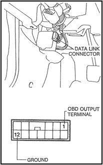
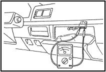
WITHOUT A SCAN TOOL
1. Remove the under dash cover, if equipped. 2.
Attach an analog voltmeter between the on-board diagnostic output
terminal of the data link connector and the ground terminal. 3. Turn the ignition switch ON. 4. Read the on-board diagnostic output pattern from the voltmeter and record. 5. Diagnose and repair the faulty components as required. 6. Erase the trouble code. 7. Turn the ignition switch ON, and read the diagnostic trouble codes, checking that a normal code is output.
TROUBLE CODES Code 11 Oxygen sensor Code 12 Air flow sensor Code 13 Intake Air Temperature Sensor Code 14 Throttle position Sensor (TPS) Code 15 SC Motor position Sensor (MPS) Code 21 Engine Coolant Temperature Sensor Code 22 Crank angle sensor Code 23 No.1 cylinder TOC (camshaft position) Sensor Code 24 Vehicle speed sensor Code 25 Barometric pressure sensor Code 31 Knock sensor (KS) Code 32 Manifold pressure sensor Code 36 Ignition timing adjustment signal Code 39 Oxygen sensor (rear-turbocharged) Code 41 Injector Code 42 Fuel pump Code 43 EGR Code 44 Ignition Coil: Power transistor unit (No. 1 and No.4 cylinders) on 3.0L Code 52 Ignition Coil; Power transistor unit (No. 2 and No.5 cylinders) on 3.0L Code 53 Ignition Coil; Power transistor unit (No. 3 and No.6 cylinders) on 3.0L Code 55 AC valve position sensor Code 59 Heated oxygen sensor Code 61 Transaxle control unit cable (automatic transmission) Code 62 Warm-up control valve position sensor (non-turbo)
Vše
nej v novém roce 2006 Potřeboval bych poradit, mám Galanta 2.0 TD,
r.v.93, Mám ho asi 14 dnů a má spotřebu 13 - 15 l/100 km při běžném
klidném provozu. Nemá orig. vzduch filtr, jen konusový tuning filtr
nasazen na hadicí sání k turbu. Ještě si bere olej, ale to bych typoval
na těsnění dříků ventilů. Tlaky motoru jsou od 30 po 34 bar. Což by
mělo být OK. Poradí mi někdo co s tím? Díky Jara feller@seznam.cz