DTC B2321 Driver Side Door ECU Communication Stop |
| DTC No. | DTC Detection Condition | Trouble Area |
| B2321 | No communication between power window regulator motor assembly (for driver side) and main body ECU (multiplex network body ECU) for 10 seconds or more. |
|
| 1.CHECK DTC OUTPUT |
Clear the DTC (Click here).
Recheck for DTCs.
| Result | Proceed to |
| Only DTC B2321 is output. | A |
| DTC B1206 and B2321 are output simultaneously. | B |
|
| ||||
| A | |
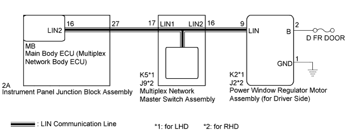
| 2.CHECK HARNESS AND CONNECTOR (MASTER SWITCH - DRIVER SIDE POWER WINDOW REGULATOR MOTOR) |
Disconnect the K5*1 or J9*2 multiplex network master switch connector.
Disconnect the K2*1 or J2*2 power window regulator motor (for driver side) connector.
Measure the resistance according to the value(s) in the table below.
| Tester Connection | Condition | Specified Condition |
| K5-16 (LIN2) - K2-9 (LIN)*1 J9-16 (LIN2) - J2-9 (LIN)*2 | Always | Below 1 Ω |
| K5-16 (LIN2) - Body ground*1 J9-16 (LIN2) - Body ground*2 | Always | 10 kΩ or higher |
|
| ||||
| OK | |
| 3.INSPECT MULTIPLEX NETWORK MASTER SWITCH ASSEMBLY |
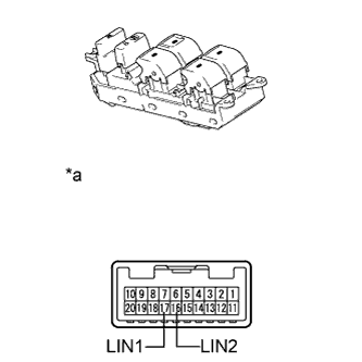 |
Remove the multiplex network master switch assembly (Click here).
Measure the resistance according to the value(s) in the table below.
| Tester Connection | Condition | Specified Condition |
| 16 (LIN2) - 17 (LIN1) | Always | Below 1 Ω |
| 16 (LIN2) - Body ground | Always | 10 kΩ or higher |
| *a | Component without harness connected (Multiplex Network Master Switch Assembly) |
|
| ||||
| OK | |
| 4.CHECK HARNESS AND CONNECTOR (POWER WINDOW REGULATOR MOTOR - BATTERY, BODY GROUND) |
Measure the voltage according to the value(s) in the table below.
| Tester Connection | Condition | Specified Condition |
| K2-2 (B) - Body ground*1 J2-2 (B) - Body ground*2 | Power switch off | 11 to 14 V |
Measure the resistance according to the value(s) in the table below.
| Tester Connection | Condition | Specified Condition |
| K2-1 (GND) - Body ground*1 J2-1 (GND) - Body ground*2 | Always | Below 1 Ω |
|
| ||||
| OK | |
| 5.REPLACE POWER WINDOW REGULATOR MOTOR ASSEMBLY (for DRIVER SIDE) |
Replace the power window regulator motor assembly (for driver side) (Click here).
| NEXT | |
| 6.CHECK DTC OUTPUT |
Clear the DTC (Click here).
Check for DTCs.
|
| ||||
| OK | ||
| ||
