SRS Indicator Circuit Troubleshooting
SRS Indicator Circuit Troubleshooting
The SRS Indicator Doesn't Come On
| 1. | Turn the ignition switch ON (II), and check to see if the other indicators come on (brake system, etc). Do the other indicators come on? YES - Go to 2. NO - Go to 8. |
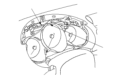
| 2. | Turn the ignition switch OFF, then disconnect C2 connector (A), and C1 [C3] connector (B) from the gauge assembly. [ ]: With daytime lighting
 BA BA |
| 3. | Check resistance between the No. 19 terminal of C2 connector and body ground. There should be 0-1 W.
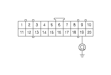 C2 CONNECTORWire side of female terminalsBLK C2 CONNECTORWire side of female terminalsBLKIs the resistance as specified? YES - Go to 4. NO - Open in the BLK wire of the dashboard wire harness or faulty body ground terminal (G401). If the body ground terminal is OK, replace the dashboard wire harness.n |
| 4. | Check for voltage between the No. 27 [No. 31] terminal of C1 [C3] connector and body ground within the first 6 seconds after turning the ignition switch ON (II). There should be 8.5 V or less. [ ]: With daytime lighting
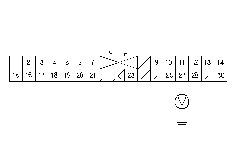 C1 CONNECTORWire side of female terminalsPNK C1 CONNECTORWire side of female terminalsPNK
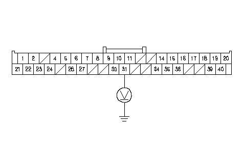 C3 CONNECTORWire side of female terminalsPNK C3 CONNECTORWire side of female terminalsPNKIs the voltage as specified? YES - Faulty SRS indicator circuit in the gauge assembly; replace the gauge assembly.n NO - Go to 5. |
| 5. | Turn the ignition switch OFF. |
| 6. | Disconnect the U1o connector (A) from the SRS unit.
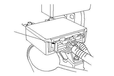 A A |
| 7. | Connect a voltmeter between the No. 27 [No. 31] terminal (+) of C1 [C3] connector and body ground. Turn the ignition switch ON (II), and measure voltage. There should be 0.5 V or less. [ ]: With daytime lighting
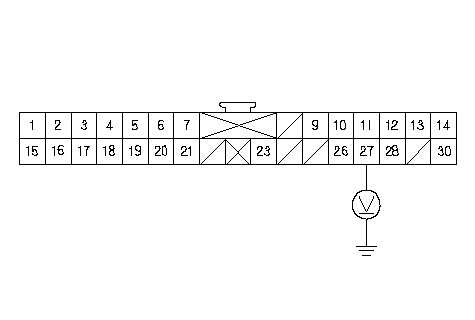 C1 CONNECTORWire side of female terminalsPNK C1 CONNECTORWire side of female terminalsPNK
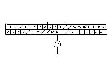 C3 CONNECTORWire side of female terminalsPNK C3 CONNECTORWire side of female terminalsPNKIs the voltage as specified? YES - Faulty SRS unit; replace the SRS unit.n NO - Short to power in the PNK wire of the dashboard wire harness; replace the faulty harness.n |
| 8. | Turn the ignition switch OFF. Check the No. 3 ( 7.5A) fuse in the under-dash fuse/relay box. Did No. 3 (7.5A) fuse blow? YES - Go to 11. NO - Go to 9. |
| 9. | Disconnect C2 connector (A) from the gauge assembly.
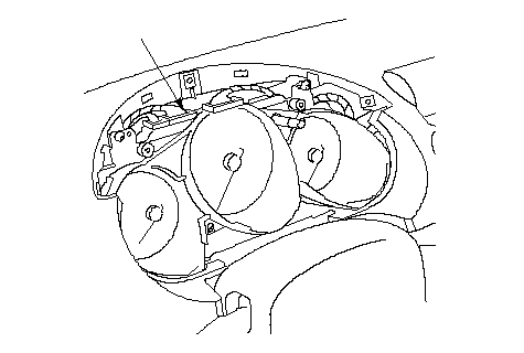 A A |
| 10. | Connect a voltmeter between the No. 2 terminal of C2 connector and body ground. Turn the ignition switch ON (II), and measure the voltage. There should be battery voltage.
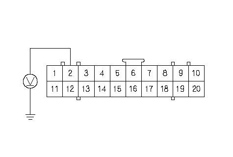 C2 CONNECTORWire side of female terminalsYEL C2 CONNECTORWire side of female terminalsYELIs there battery voltage? YES - Faulty SRS indicator circuit in the gauge assembly or poor contact at gauge assembly connector B (20P) and gauge assembly; if the connection is OK, replace the gauge assembly.n NO - Open in the under-dash fuse/relay box No. 3 ( 7.5A) fuse line, or open in the YEL wire of dashboard wire harness. If the under-dash fuse/relay box is OK, replace the faulty harness.n |
| 11. | Replace the No. 3 (7.5A) fuse, and check to see if the SRS indicator comes on. Does the SRS indicator come on? YES - The system is OK at this time.n NO - Repair the short to ground in the under-dash fuse/relay box No. 3 (7.5A) fuse line.n |
The SRS Indicator Stays On When In ‘‘SCS'' Menu Method
NOTE:
- Inability to retrieve DTCs with the HDS. Retrieve the flash codes with the SCS mode.
- A new SRS unit must sense the entire system is OK before completing its initial self-test. The most common cause of an incomplete self-test is the failure to replace all deployed parts after a collision, in particular, seat belt tensioners and seat belt buckle tensioners.
- An incomplete self-test prevents the HDS from retrieving DTCs, although flash codes are available in the SCS mode.
| 1. | Erase the DTC memory. Does the SRS indicator go off when the DTC memory is erased? YES - Go to 43. NO - Go to 2. |
| 2. | Check the No. 13 (10A) fuse in the under-dash fuse/relay box. Is the fuse OK? YES - Go to 20. NO - Go to 3. |
| 3. | Replace the No. 13 (10A) fuse in the under-dash fuse/relay box. |
| 4. | Turn the ignition switch ON (II), and wait for 30 seconds. Then turn the ignition switch OFF. |
| 5. | Check the No. 13 (10A) fuse in the under-dash fuse/relay box. Is the fuse OK? YES - The system is OK at this time.n NO - Go to 6. |
| 6. | Replace the No. 13 (10A) fuse in the under-dash fuse/relay box. |
| 7. | Disconnect the battery negative cable, and wait for 3 minutes. |
| 8. | Disconnect the D1i connector (A).
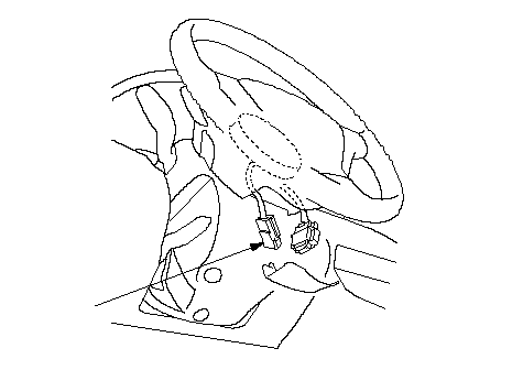 A A |
| 9. | Disconnect the P1o connector (A).
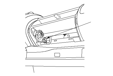 A A |
| 10. | Disconnect the TL1o and TR1o connectors. |
| 11. | Disconnect U1o connector (A) from the SRS unit.
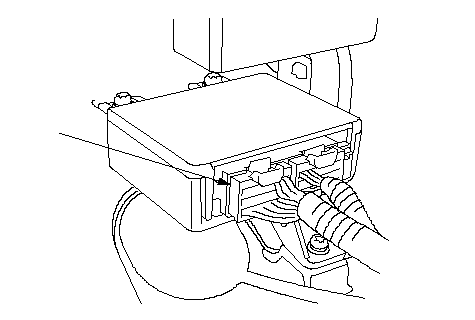 A A |
| 12. | Disconnect the TBLo and TBRo connectors (A).
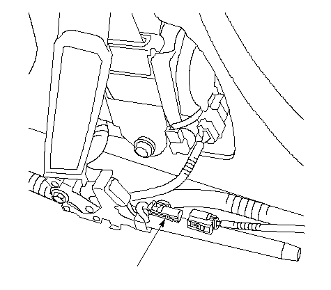 A A |
| 13. | Reconnect the negative battery cable. |
| 14. | Turn the ignition switch ON (II), and wait for 30 seconds. Then turn the ignition switch OFF. |
| 15. | Check the No. 13 (10A) fuse in the under-dash fuse/relay box. Is the fuse OK? YES - Short to ground in the SRS unit; replace the SRS unit.n NO - Go to 16. |
| 16. | Replace the No. 13 (10A) fuse in the under-dash fuse/relay box. |
| 17. | Disconnect the dashboard wire harness connector I from the under-dash fuse/relay box. |
| 18. | Turn the ignition switch ON (II), and wait for 30 seconds. Then turn the ignition switch OFF. |
| 19. | Check the No. 13 (10A) fuse in the under-dash fuse/relay box. Is the fuse OK? YES - Short to ground in the dashboard wire harness; replace the dashboard wire harness.n NO - Repair the short to ground in the under-dash fuse/relay box No. 13 (10A) fuse line; replace the under-dash fuse/relay box or repair it.n |
| 20. | Disconnect the battery negative cable, and wait for 3 minutes. |
| 21. | Disconnect the D1i connector (A).
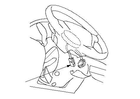 A A |
| 22. | Disconnect the P1o connector (A).
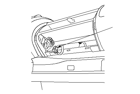 A A |
| 23. | Disconnect the TL1o and TR1o connectors. |
| 24. | Disconnect U1o connector (A) from the SRS unit.
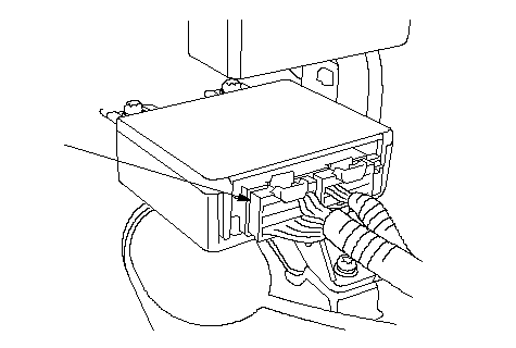 A A |
| 25. | Disconnect the TBLo and TBRo connectors (A).
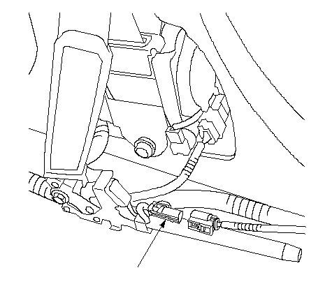 A A |
| 26. | Reconnect the battery negative cable. |
| 27. | Connect a voltmeter between the No. 18 terminal of U1o connector and body ground. Turn the ignition switch ON (II), and measure the voltage. There should be battery voltage.
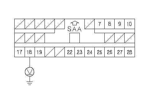 U1o CONNECTORWire side of female terminalsPNK U1o CONNECTORWire side of female terminalsPNKIs there battery voltage? YES - Go to 31. NO - Go to 28. |
| 28. | Turn the ignition switch OFF. |
| 29. | Disconnect the dashboard wire harness connector I (2P) from the under-dash fuse/relay box. |
| 30. | Check resistance between the No. 18 terminal of U1o connector and the No. 1 terminal of the dashboard wire harness connector I (2P). There should be 0-1 W.
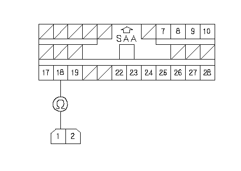 U1o CONNECTORWire side of female terminalsDASHBOARD WIRE HARNESS U1o CONNECTORWire side of female terminalsDASHBOARD WIRE HARNESSCONNECTOR I (2P)PNKPNK Is the resistance as specified? YES - Open in the under-dash fuse/relay box or poor contact at the dashboard wire harness connector I (2P); check the connection. If the connection is OK, replace the under-dash fuse/relay box.n NO - Open in the dashboard wire harness; replace the dashboard wire harness.n |
| 31. | Turn the ignition switch OFF. |
| 32. | Connect the No. 18 terminal and the No. 19 terminal of the U1o connector with a jumper wire.
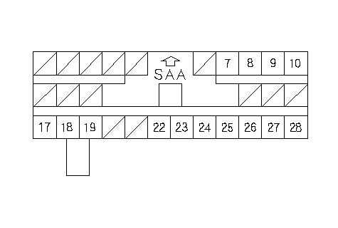 U1o CONNECTORWire side of female terminalsJUMPER WIRE U1o CONNECTORWire side of female terminalsJUMPER WIRE |
| 33. | Turn the ignition switch ON (II). |
| 34. | Check the SRS indicator. Does the SRS indicator go off? YES - Faulty SRS unit; replace the SRS unit.n NO - Go to 35. |
| 35. | Turn the ignition switch OFF. |
| 36. | Disconnect the jumper wire between the No. 18 terminal and the No. 19 terminal of the U1o connector. |
| 37. | Check the No. 13 (10A) fuse in the under-dash fuse/relay box. Is the fuse OK? YES - Go to 41. NO - Go to 38. |
| 38. | Replace the No. 13 (10A) fuse in the under-dash fuse/relay box. |
| 39. | Disconnect C1 connector (A) from the gauge assembly.
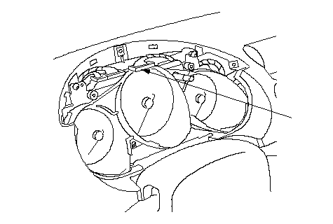 A A |
| 40. | Check resistance between the No. 19 terminal of U1o connector and body ground. There should be an open circuit, or at least 1 MW.
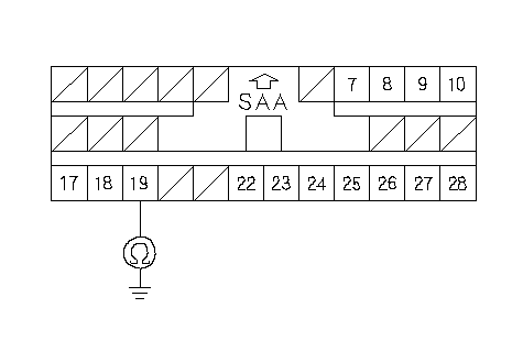 PNKU1o CONNECTORWire side of female terminals PNKU1o CONNECTORWire side of female terminalsIs the resistance as specified? YES - Faulty SRS indicator circuit in the gauge assembly; replace the gauge assembly.n NO - Short to ground in the dashboard wire harness; replace the dashboard wire harness.n |
| 41. | Disconnect C1 connector (A) from the gauge assembly.
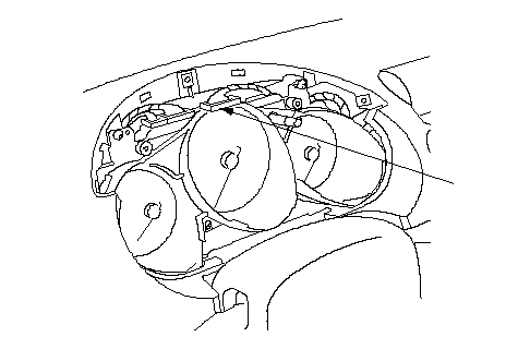 A A |
| 42. | Check resistance between the No. 27 [No.31] terminal of C1 [C3] connector and the No. 19 terminal of U1o connector. There should be 1 W or less. [ ]: With daytime lighting
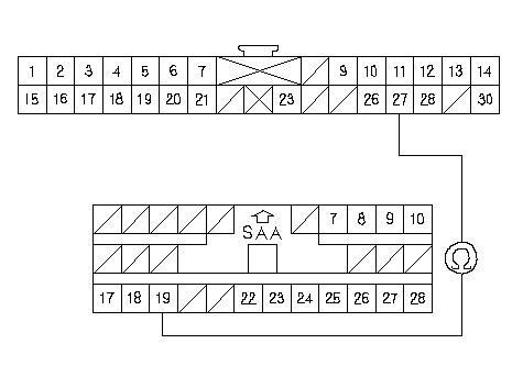 C1 CONNECTORWire side of female terminalsWire side of female terminalsU1o CONNECTORPNKPNK C1 CONNECTORWire side of female terminalsWire side of female terminalsU1o CONNECTORPNKPNK
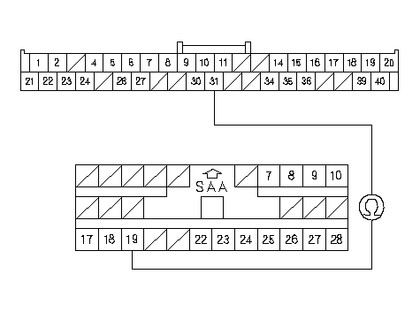 C3 CONNECTORWire side of female terminalsWire side of female terminalsU1o CONNECTORPNKPNK C3 CONNECTORWire side of female terminalsWire side of female terminalsU1o CONNECTORPNKPNKIs the resistance as specified? YES - Faulty SRS indicator circuit in the gauge assembly or poor contact at the C1 [C3] connector ; check the connection. If the connection is OK, replace the gauge assembly.n[ ]: With daytime lighting NO - Open in the dashboard wire harness; replace the dashboard wire harness.n |
| 43. | Disconnect U1o connector (A) from the SRS unit.
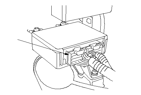 A A |
| 44. | Connect the HDS to the Data Link Connector (16P), and follow the prompts in the ‘‘SCS'' menu. |
| 45. | Check resistance between the No. 26 terminal of U1o connector and body ground. There should be 0-1.0 W.
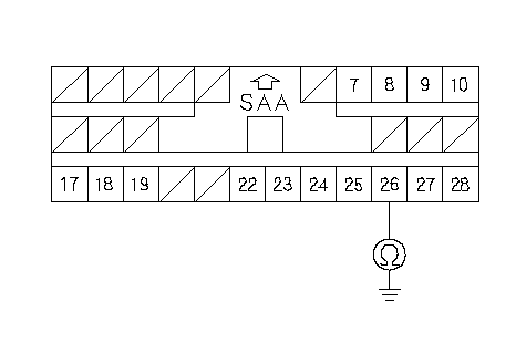 U1o CONNECTORWire side of female terminalsBRN U1o CONNECTORWire side of female terminalsBRNIs the resistance as specified? NO - Open in the SCS line between the No. 26 terminal of U1o connector and the No. 9 terminal (BRN wire) of the Data Link Connector (DLC) (16P) or open between the No. 4 terminal of the Data Link Connector (DLC) (16P) and body ground. Repair the open wire(s).n |