Interlock System - Shift Lock System Circuit Troubleshooting (L12A/L13A CVT)
Interlock System - Shift Lock System Circuit Troubleshooting
| 1. | Press the brake pedal. Are the brake lights ON? YES - Go to 2. NO - Repair faulty brake pedal circuit.n |
| 2. | Disconnect PCM connectors A (31P) and E (31P). |
| 3. | Press the brake pedal, and measure the voltage between PCM connector terminals E22 and A23 or A24.
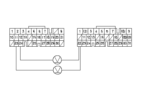 PCM CONNECTORSA (31P)E (31P)LG1 (BRN/YEL)LG2 (BRN/YEL)Wire side of female terminalsBK SW (WHT/BLK) PCM CONNECTORSA (31P)E (31P)LG1 (BRN/YEL)LG2 (BRN/YEL)Wire side of female terminalsBK SW (WHT/BLK)Is there battery voltage? YES - Release the brake pedal, then go to 4. NO - Repair open in the wire between PCM connector terminal E22 and the brake pedal position switch.n |
| 4. | Turn the ignition switch ON (II). |
| 5. | Press the brake pedal, and measure the voltage between PCM connector terminals E13 and A23 or A24.
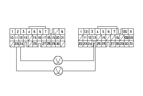 PCM CONNECTORSA (31P)E (31P)LG1 (BRN/YEL)LG2 (BRN/YEL)Wire side of female terminalsSLC (WHT/BLU) PCM CONNECTORSA (31P)E (31P)LG1 (BRN/YEL)LG2 (BRN/YEL)Wire side of female terminalsSLC (WHT/BLU)Is there battery voltage? YES - Release the brake pedal, then go to 6. NO - Update the PCM if it does not have the latest software, or subsutitute a known-good PCM, then recheck. If the symptom/ indication goes away with a known-good PCM, replace the original PCM.n |
| 6. | Turn the ignition switch OFF. |
| 7. | Connect PCM connectors A (31P) and E (31P). |
| 8. | Disconnect the gauge assembly connector B (14P). |
| 9. | Turn the ignition switch ON (II). |
| 10. | Press the brake pedal, and measure the voltage between gauge assembly connector terminal B6 and body ground.
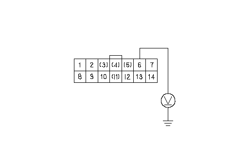 GAUGE ASSEMBLY CONNECTOR B (14P)Wire side of female terminalsSLC (WHT/BLU) GAUGE ASSEMBLY CONNECTOR B (14P)Wire side of female terminalsSLC (WHT/BLU)Is there battery voltage? YES - Release the brake pedal, then go to 15. NO - Repair open or short in the wire between PCM connector terminal E13 and the gauge assembly connector terminal B6.n |
| 11. | Turn the ignition switch OFF. |
| 12. | Disconnect the shift lock solenoid/park pin switch connector. |
| 13. | Turn the ignition switch ON (II). |
| 14. | Measure the voltage between shift lock solenoid/park pin switch connector terminal No. 1 and body ground. Do not press the accelerator pedal.
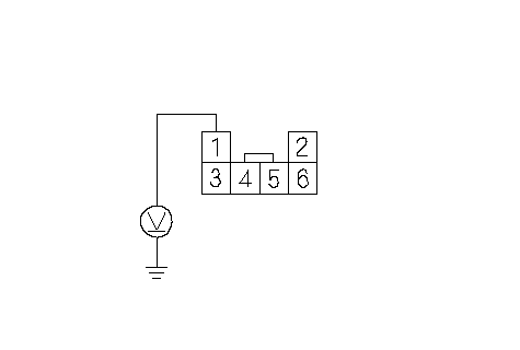 SHIFT LOCK SOLENOID/ SHIFT LOCK SOLENOID/PARK PIN SWITCH CONNECTORIG1 (YEL)Wire side of female terminals Is there battery voltage? YES - Go to 15. NO - Check for blown No. 16 fuse in under-hood fuse/relay box. If the fuse is OK, repair open or short in the wire between the shift lock solenoid connector and the under-hood fuse/relay box.n |
| 15. | Press the brake pedal, and measure the voltage between shift lock solenoid/park pin switch connector terminals No. 1 and No. 3. The shift lever must be in [P] position.
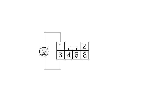 SHIFT LOCK SOLENOID/ SHIFT LOCK SOLENOID/PARK PIN SWITCH CONNECTORIG1 (YEL)Wire side of female terminalsSHIFT LOCK SOL (YEL/BLK) Is there battery voltage? YES - Go to 16. NO - Go to 17. |
| 16. | Connect the battery positive terminal to shift lock solenoid/park pin switch connector terminal No. 1, and connect the battery negative terminal to the terminal No. 3, then check that the shift lock solenoid operates. NOTE: Do not connect the battery positive terminal to the terminal No. 3 or you will damage the diode inside the shift lock solenoid.
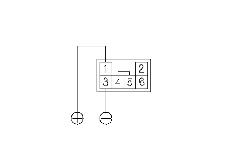 SHIFT LOCK SOLENOID/ SHIFT LOCK SOLENOID/PARK PIN SWITCH CONNECTOR(RED)Terminal side of male terminals(BLU) Does the shift lock solenoid operate properly? YES - Repair the shift lock mechanism.n NO - Replace the shift lock solenoid.n |
| 17. | Turn the ignition switch OFF. |
| 18. | Disconnect gauge assembly connector B (14P). |
| 19. | Check for continuity between gauge assembly connector terminal B1 and shift lock solenoid/park pin switch connector terminal No. 3.
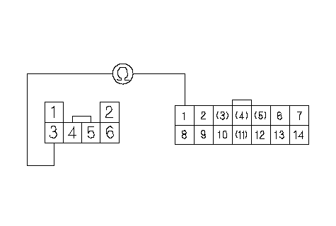 SHIFT LOCK SOLENOID/ SHIFT LOCK SOLENOID/PARK PIN SWITCH CONNECTORWire side of female terminals(YEL/BLK)GAUGE ASSEMBLY CONNECTOR B (14P)(YEL/BLK) Is there continuity? YES - Go to 20. NO - Repair open in the wire between gauge assembly connector terminal B1 and the shift lock solenoid/park pin switch connector.n |
| 20. | Check for continuity between gauge assembly connector terminal B14 and body ground while the shift lever is in [P] position, and when the shift lever in any position other than [P] and [N].
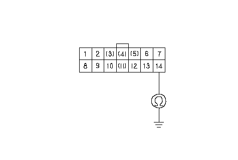 GAUGE ASSEMBLY CONNECTOR B (14P)Wire side of female terminalsATP P (BLK/BLU) GAUGE ASSEMBLY CONNECTOR B (14P)Wire side of female terminalsATP P (BLK/BLU)Is there continuity while the shift lever is in [P] position, and no continuity when the shift lever in any position other than [P] and [N]? YES - Faulty shift lock system circuit in the gauge assembly, replace the gauge assembly.n NO - Repair open in the ATP P wire between gauge assembly connector terminal B14 and the transmission range switch.n |