Engine Installation (L12A/L13A without ETCS)
Engine Installation
| 1. | Position the engine under the vehicle. Attach the chain hoist to the engine, then lift the engine into position in the vehicle.
|

| 2. | Install the front sub-frame (A), then secure the under covers with the clips (B).
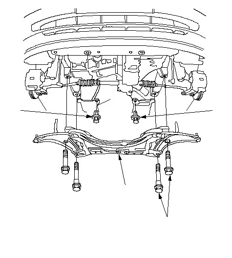 BBA14 x 1.5 mm BBA14 x 1.5 mm93 N·m (9.5 kgf·m, 69 lbf·ft) Replace. |
| 3. | Install the left front mount/bracket assembly (M/T).
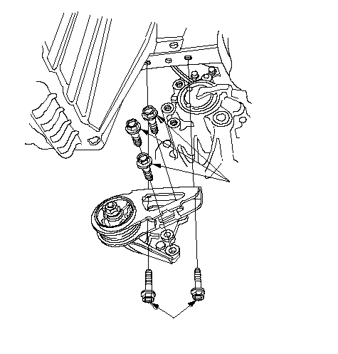 10 x 1.25 mm 10 x 1.25 mm39 N·m (4.0 kgf·m, 29 lbf·ft)10 x 1.25 mm 39 N·m (4.0 kgf·m, 29 lbf·ft) |
| 4. | Install the rear mount mounting bolts.
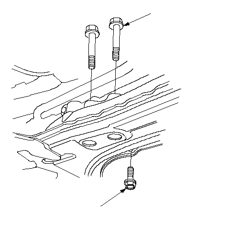 10 x 1.25 mm 10 x 1.25 mm44 N·m (4.5 kgf·m, 33 lbf·ft)10 x 1.25 mm 44 N·m (4.5 kgf·m, 33 lbf·ft) |
| 5. | Lower the hoist. |
| 6. | Loosely install the side engine mount/bracket assembly (A), then loosen the upper bracket mounting nut (B). M/T: 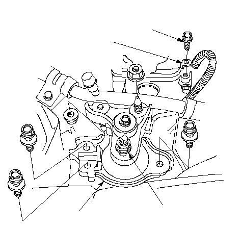 AB6 x 1.0 mm AB6 x 1.0 mm9.8 N·m (1.0 kgf·m, 7.2 lbf·ft)C CVT: 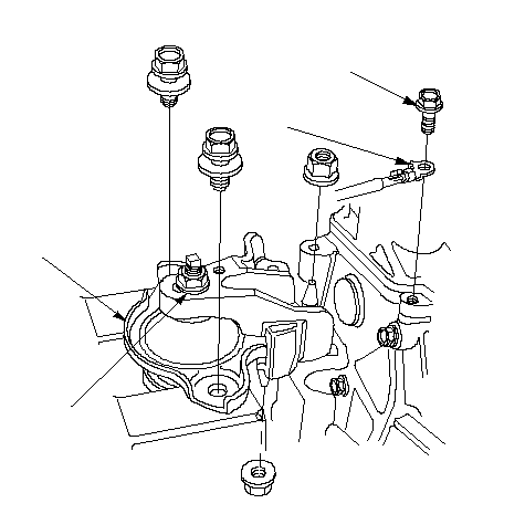 AB6 x 1.0 mm AB6 x 1.0 mm9.8 N·m (1.0 kgf·m, 7.2 lbf·ft)C |
| 7. | Install the ground cable (C). |
| 8. | Push the engine to the side engine mount side until the mount bracket contacts the stud bolt, then tighten the nut (A). Check mount-to-bracket clearance. They should be 6 mm (0.2 in.) and more. If the clearance out of tolerance, adjust the clearance.
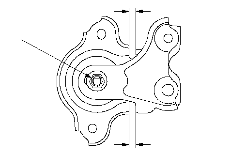 A A12 x 1.25 mm 74 N·m (7.5 kgf·m, 54 lbf·ft)6 mm (0.2 in) min.6 mm (0.2 in) min. |
| 9. | Tighten the mounting bolts (A), then tighten the support nuts (B).
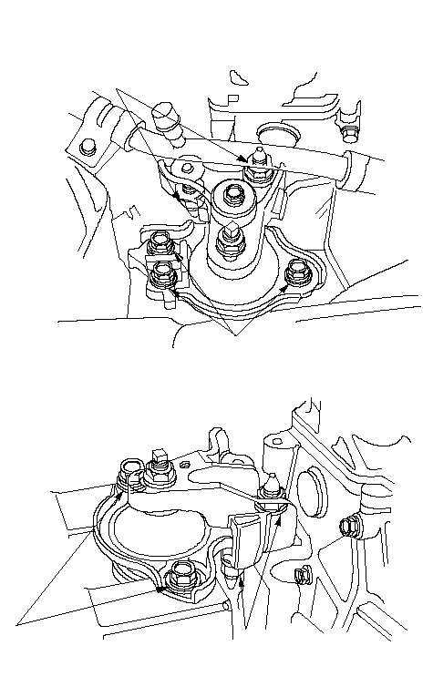 B B10 x 1.25 mm 39 N·m (4.0 kgf·m, 29 lbf·ft)M/T:CVT:A 10 x 1.25 mm 49 N·m (5.0 kgf·m, 36 lbf·ft)A 10 x 1.25 mm 49 N·m (5.0 kgf·m, 36 lbf·ft)B 10 x 1.25 mm 39 N·m (4.0 kgf·m, 29 lbf·ft) |
| 10. | Install the transmission mount bracket (A), then tighten the support bolt/nuts and mounting bolt in the numbered sequence shown. M/T: 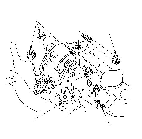 AB10 x 1.25 mm AB10 x 1.25 mm49 N·m (5.0 kgf·m, 36 lbf·ft)10 x 1.25 mm 44 N·m (4.5 kgf·m, 33 lbf·ft)(2)(1)6 x 1.0 mm 9.8 N·m (1.0 kgf·m, 7.2 lbf·ft) CVT: 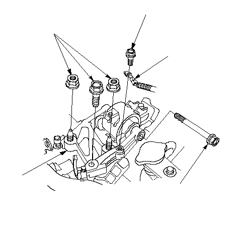 B6 x 1.0 mm B6 x 1.0 mm9.8 N·m (1.0 kgf·m, 7.2 lbf·ft)12 x 1.25 mm 49N·m (5.0 kgf·m, 36 lbf·ft)10 x 1.25 mm 44 N·m (4.5 kgf·m, 33 lbf·ft)A(2)(1) |
| 11. | Install the ground cable (B). |
| 12. | Remove the chain hoist from the engine. |
| 13. | Raise the hoist to full height. |
| 14. | Install the steering gearbox on the front sub-frame. |
| 15. | Install a new set ring on the end of each driveshaft, then install the driveshafts. Make sure each ring ‘‘clicks'' into place in the differential and intermediate shaft. |
| 16. | Connect the suspension lower arm ball joints. |
| 17. | Connect the stabilizer links. |
| 18. | Install the Three Way Catalytic Converter (TWC) (A); use new gaskets (B) and new self locking nuts (C).
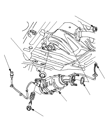 DAEC DAEC10 x 1.25 mm 31 N·m (3.2 kgf·m, 23 lbf·ft)8 x 1.25 mm 22 N·m (2.2 kgf·m, 16 lbf·ft)BB |
| 19. | Connect the primary Heated Oxygen Sensor (primary HO2S) connector (D) (except KU model) or Heated Oxygen Sensor (HO2S) connector (D) (KU model). |
| 20. | Connect the secondary Heated Oxygen Sensor (secondary HO2S) connector (E) (except KU model). |
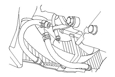
| 21. | Install the Automatic Transmission Fluid (ATF) cooler hoses (CVT).
 |
| 22. | Install the condenser fan shroud. |
| 23. | Install the A/C compressor (A), then connect the compressor clutch connector (B).
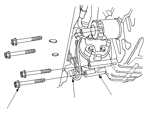 BA8 x 1.25 mm BA8 x 1.25 mm24 N·m (2.4 kgf·m, 17 lbf·ft) |
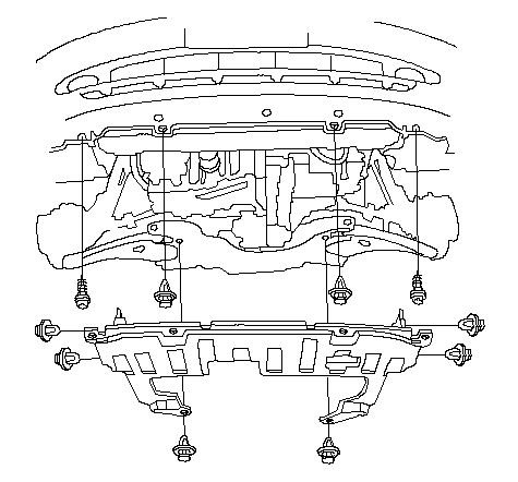
| 24. | Install the splash shield.
 |
| 25. | Lower the hoist. |
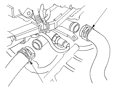
| 26. | Install the upper radiator hose (A) and lower radiator hose (B).
 AB AB |
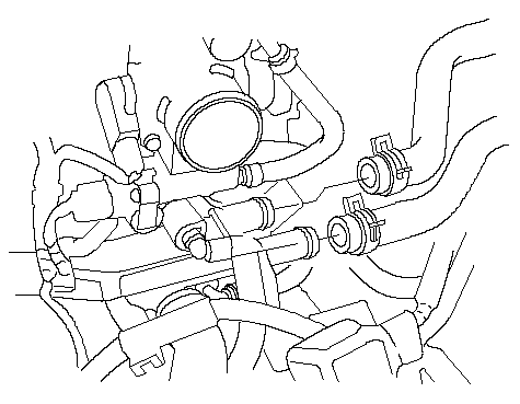
| 27. | Install the heater hoses.
 |
| 28. | Install the shift cable (A) using the plastic washer (B), washer (C), and new cotter pin (D) (CVT).
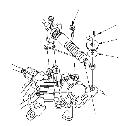 DCBA8 x 1.25 mm DCBA8 x 1.25 mm25 N·m (2.6 kgf·m, 19 lbf·ft) |
| 29. | Install the select cable (A) and shift cable (B) using the plastic washers (C), washers (D), and new cotter pins (E) (M/T).
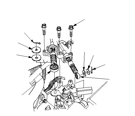 EB8 x 1.25 mm EB8 x 1.25 mm27 N·m (2.8 kgf·m, 20 lbf·ft)EDCCDA |
| 30. | Install the clutch slave cylinder (A) and clutch line bracket mounting bolt (B) (M/T).
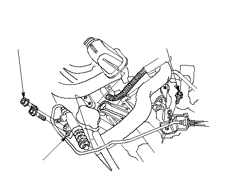 A8 x 1.25 mm A8 x 1.25 mm22 N·m (2.2 kgf·m, 16 lbf·ft)B 6 x 1.0 mm 9.8 N·m (1.0 kgf·m, 7.2 lbf·ft) |
| 31. | Install the Evaporative Emission (EVAP) canister hose (A) and brake booster vacuum hose (B).
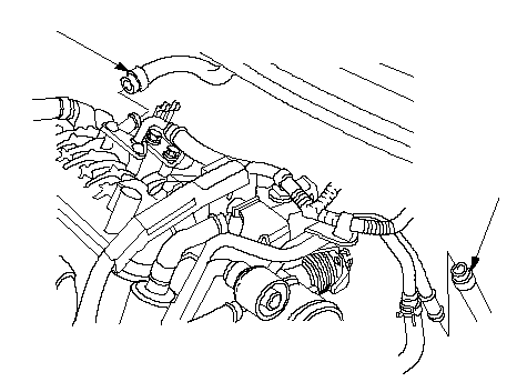 BA BA |
| 32. | Install the battery cables (A) on the under-hood fuse/relay box, then install the harness clamp(s) (B). LHD models: 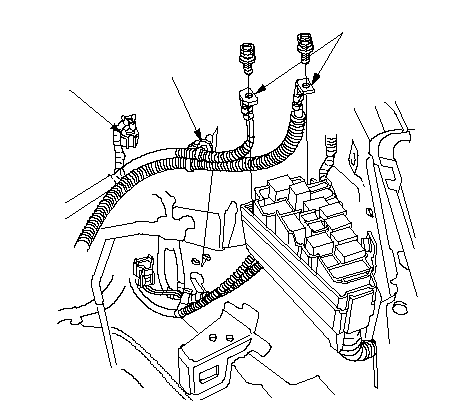 CBA CBARHD models: 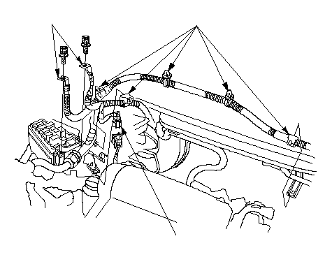 ABC ABC |
| 33. | Connect the wire harness connector (C). |
| 34. | Push the Engine Control Module (ECM)/Powertrain Control Module (PCM) connectors through the bulkhead, then install the grommet (A). LHD models: 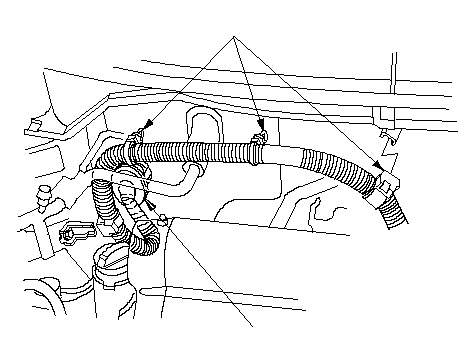 BA BARHD models: 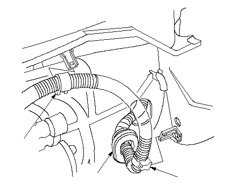 BAB BAB |
| 35. | Install the harness clamps (B). |
| 36. | Connect the ECM/PCM connectors (A) and main wire harness connector (B). LHD models: 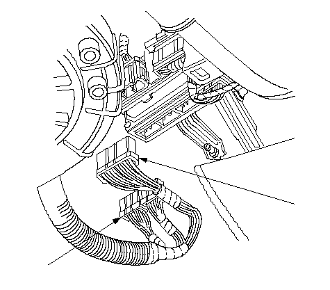 AB ABRHD models: 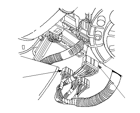 AB AB |
| 37. | Install the battery base (A), then install the harness clamps (B).
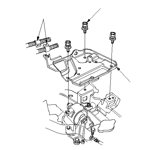 AB8 x 1.25 mm AB8 x 1.25 mm22 N·m (2.2 kgf·m, 16 lbf·ft) |
| 38. | Install air cleaner housing. |
| 39. | Install the battery. |
| 40. | Install the throttle cable, then adjust the cable. |
| 41. | Install the fuel feed hose. |
| 42. | Install the drive belt and adjust it. |
| 43. | Clean the battery posts and cable terminals with sandpaper, then assemble them and apply grease to prevent corrosion. |
| 44. | Check that the transmission shifts into gear smoothly (M/T). |
| 45. | Move the shift lever to each gear, and verify that the A/T gear position indicator follows the transmission range switch (CVT). |
| 46. | Inspect for fuel leaks. Turn the ignition switch ON (II) (do not operate the starter) so that the fuel pump runs for about 2 seconds and pressurizes the fuel line. Repeat this operation two or three times, then check for fuel leakage at any point in the fuel line. |
| 47. | Refill the engine with engine oil. |
| 48. | Refill the transmission with fluid: |
| 49. | Refill the radiator with engine coolant, and bleed air from the cooling system with the heater valve open. |
| 50. | Inspect the idle speed. |
| 51. | Inspect the ignition timing. |
| 52. | Check the wheel alignment. |