Dashboard Removal/Installation
Dashboard Removal/Installation
For some models: SRS components are located in this area. Review the SRS component locations and the precautions and procedures before performing repairs or service.NOTE:
- When prying components, use the handy remover set, or equivalent.
- Have an assistant help you when removing and installing the dashboard.
- Take care not to scratch the dashboard, body and other related parts.
- Put on gloves to protect your hands.
| 1. | If equipped with airbags, disconnect the negative cable from the battery, and wait at least 3 minutes before beginning work. |
| 2. | Remove these items: |
| 3. | Remove the nuts securing the fuse/relay box (A), then lower it. LHD is shown, RHD is symilar.
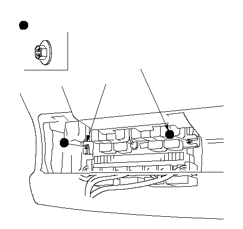 AFastener LocationsFastener Locations: Nut, 26 x 1.0 mm AFastener LocationsFastener Locations: Nut, 26 x 1.0 mm9.8 N·m (1.0 kgf·m, 7.2 lbf·ft) |
| 4. | Remove the rear heater upper duct. LHD is shown, RHD is symmetrical.
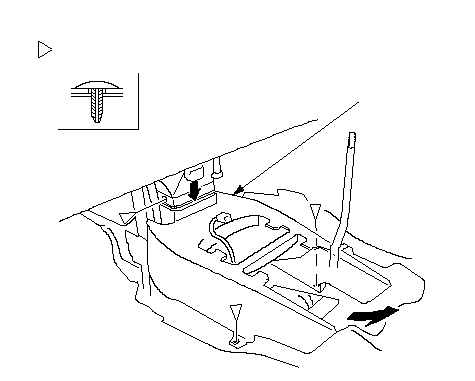 AFastener LocationsFastener Locations: Clip, 3 AFastener LocationsFastener Locations: Clip, 3 |
Under-dash fuse/relay box
| 5. | Disconnect the engine compartment wire harness connector (A), floor wire harness connectors (B), interior wire harness connector (C), door wire harness connector (D), and EPS sub wire harness connector (E) from the under-dash fuse/relay box (F). LHD (front) 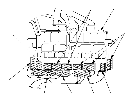 AAAEBBFCD AAAEBBFCDLHD (back) 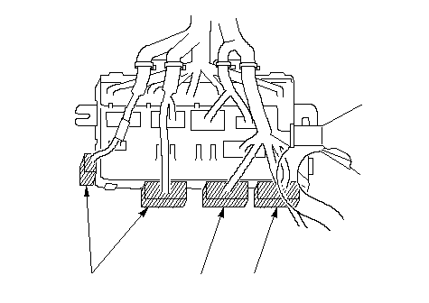 AAB AABRHD (front) 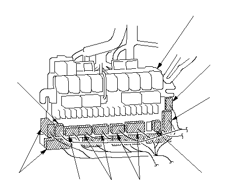 AAAEBFCDC AAAEBFCDCRHD (back) 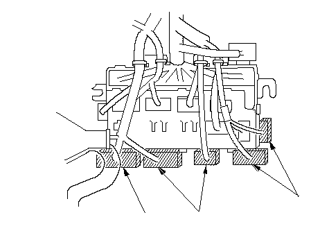 AAB AAB |
Driver's side
| 6. | From under the dash, disconnect the driver's door wire harness connectors (A) and brake switch connector (B). LHD 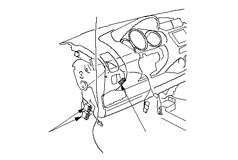 AB ABRHD 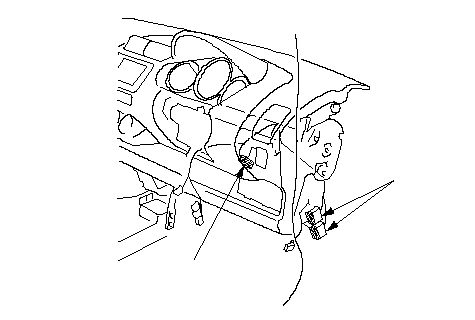 AB AB |
Middle portion (shift lever portion)
| 7. | Disconnect the parking brake switch connector (A), shift clock solenoid connector (B) (CVT models), fuel pump connector (C), SRS control unit connector (D), and secondary heated oxygen sensor connector (E). Using a Torx T30 bit, remove the ground bolt (F).
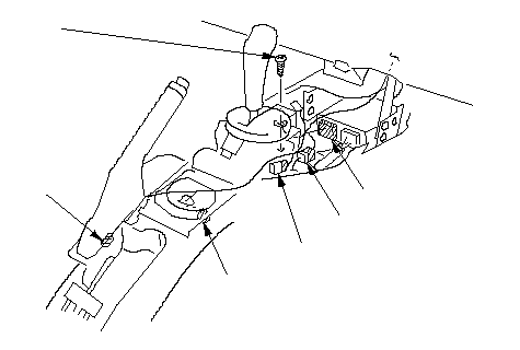 F F6 x 1.0 mm 9.8 N·m (1.0 kgf·m, 7.2 lbf·ft)DEBCA |
Middle portion (passenger's side)
| 8. | In the inner glove box opening, disconnect the recirculation control cable (A), mode control cable (B), heater sub harness connectors (C), and from under the dashboard, disconnect the air mix control cable (D):
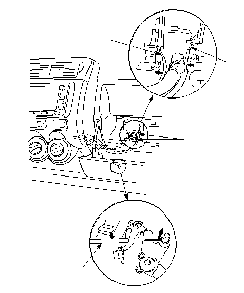 DCBA DCBA |
Passenger's side
| 9. | From under the dash, disconnect the ECM/PCM connector (A), engine wire harness connector (B), passenger's door wire harness connectors (C), front SRS sensor sub wire harness connector (D), inertia switch connector (E) (for some models), and antenna lead (F). If equipped, remove the super locking relay(G) from the bracket. LHD 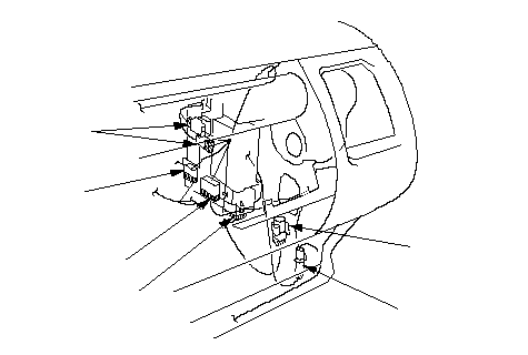 DBCAFE DBCAFERHD 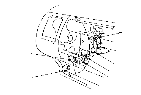 EFCGBDA EFCGBDA |
| 10. | Detach all of the harness and connector clips. |
| 11. | Remove the bolts, then remove the brake pedal support member (A). LHD is shown, RHD is symmetrical.
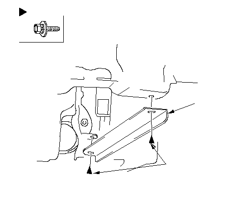 : Bolt, 28 x 1.25 mm : Bolt, 28 x 1.25 mm22 N·m (2.2 kgf·m, 16 lbf·ft)A |
| 12. | Remove the special bolts (A) from outside the passenger's door. LHD is shown, RHD is symmetrical:
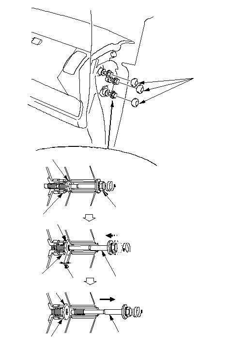 BACDCDEAADC BACDCDEAADC |
| 13. | If the adjusting nut didn't be screwed into the sleeve fully while removing the special bolts, screw its left-hand male screw into the sleeve with 21 mm open-end wrench:
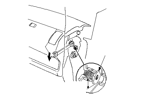 A21 mm A21 mm(0.83 in.) |
| 14. | From outside the driver's door, remove the caps (A), then remove the bolts (B, C). But the forward B Bolt is not able to remove from the body because the driver's door will interfere. LHD is shown, RHD is symmetrical.
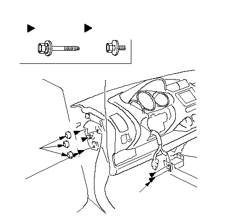 Fastener Locations: Bolt, 3BC: Bolt, 2BBBACC8 x 1.25 mm Fastener Locations: Bolt, 3BC: Bolt, 2BBBACC8 x 1.25 mm22 N·m (2.2 kgf·m, 16 lbf·ft)8 x 1.25 mm 22 N·m (2.2 kgf·m, 16 lbf·ft) |
| 15. | Open the driver's and passenger's door until one-half position, then pull both remaining forward bolts (A) outward. LHD is shown, RHD is symmetrical.
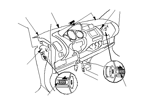 EAFAFFF EAFAFFF |
| 16. | Lift up on the dashboard (E) to release it from the guide pins (F). |
| 17. | Have an assistant holding the dashboard apart from the body, open one side door fully. Carefully remove the dashboard through the front door opening. Take care not to scratch the body with the adjusting nuts on passenger's side. |
| 18. | Install the dashboard in the reverse order of removal, and note these items:
Special bolt tightening on passenger's side
Special bolt tightening on passenger's side 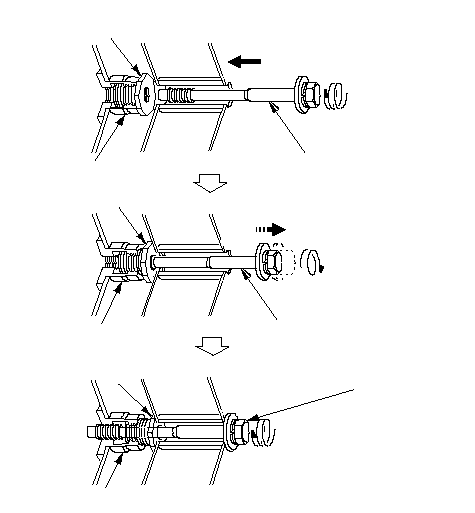 BCBCBCAAA BCBCBCAAA8 x 1.25 mm 22 N·m (2.2 kgf·m, 16 lbf·ft) |