Driveshaft Reassembly
Driveshaft Reassembly
Exploded View
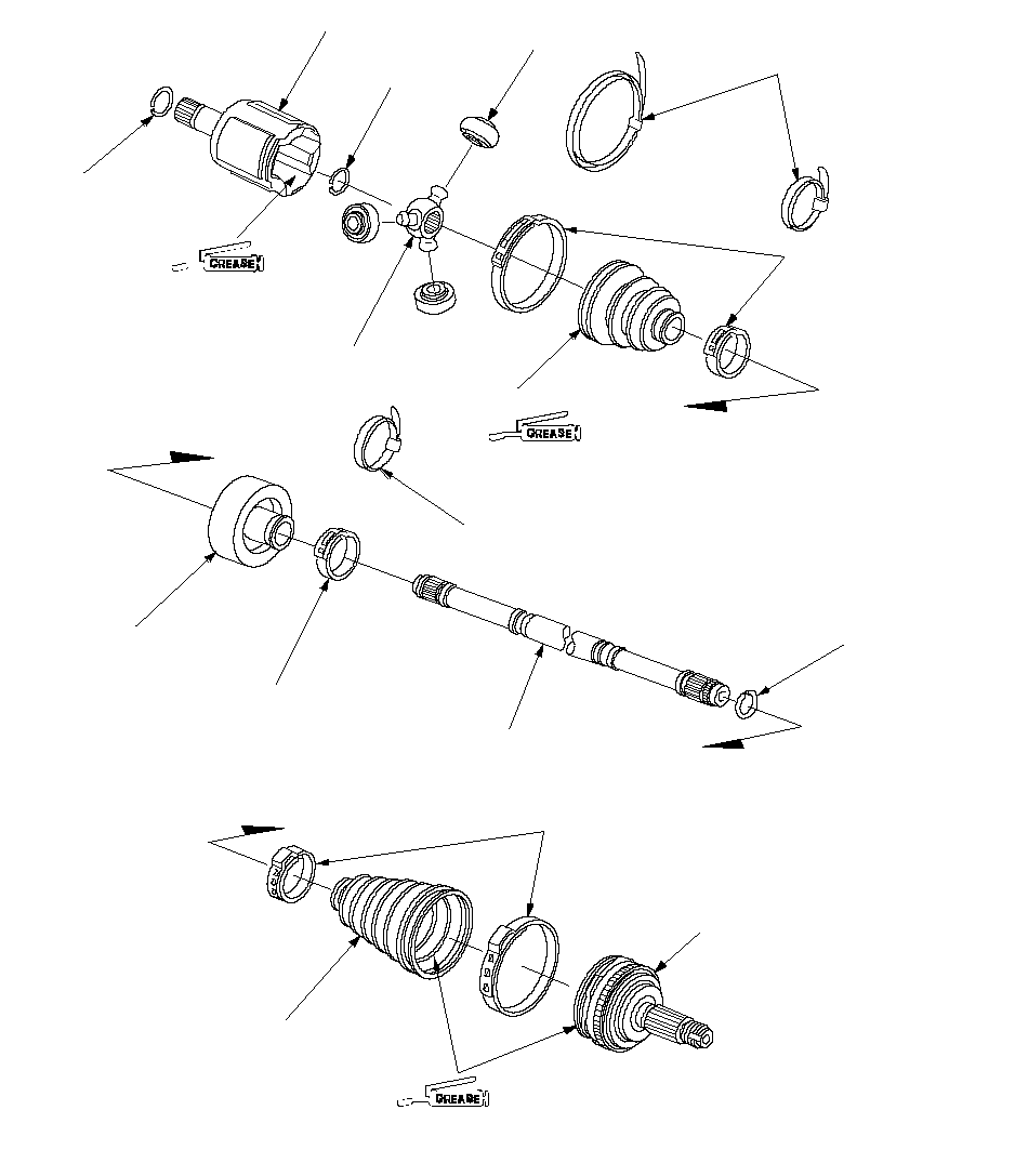 Use the grease included
in the inboard boot set.SET RING
Replace.INBOARD JOINTCIRCLIPSPIDERROLLERLOW PROFILE BAND
Replace.INBOARD BOOTUse the grease included
in the inboard boot set.DRIVESHAFTSTOP RING
Replace.DYNAMIC DAMPER
(Right driveshaft)EAR CLAMP BANDS
Replace.OUTBOARD JOINTOUTBOARD BOOT (TPE)Use the grease included
in the outboard boot set.DOUBLE LOOP BAND
Replace.
(Dynamic damper band replace only.)DOUBLE LOOP BAND
Replace.
(Boot band replace only.)LOW PROFILE BAND
Replace.
Special Tools Required
Boot band tool, ( KD-3191
or equivalent commercially available)
Boot band pincers, ( Kent-Moore J-35910
or equivalent commercially available)
NOTE: Refer to the Exploded View as needed during this procedure.
Inboard Joint Side
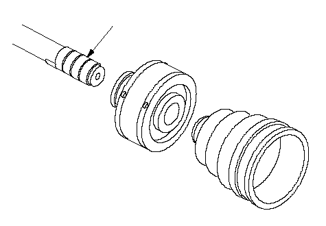
| 1. | Wrap the splines with vinyl tape (A) to prevent damage to the inboard boot and dynamic damper.
 A A |
| 2. | Install the dynamic damper and inboard boot onto the driveshaft, then remove the vinyl tape. Be careful not to damage the inboard boot and dynamic damper. |
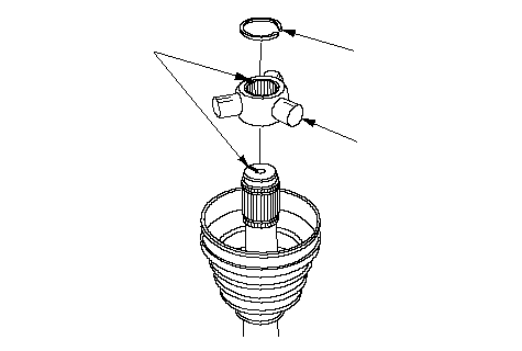
| 3. | Install the spider (A) onto the driveshaft by aligning the marks (B) on the spider and the end of the driveshaft.
 CAB CAB |
| 4. | Install the circlip (C) into the driveshaft groove. Rotate the circlip in its groove to make sure it is fully seated. |
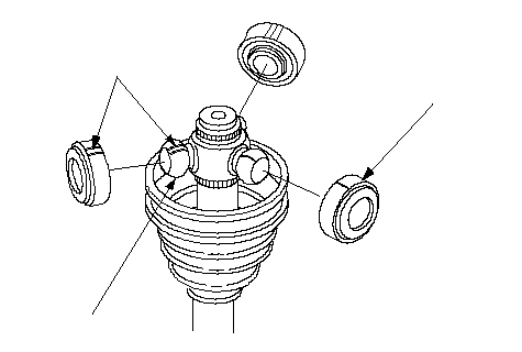
| 5. | Fit the rollers (A) onto the spider (B) with their high shoulders facing outward, and note these items:
 ABC ABC |
| 6. | Pack the inboard joint with the joint grease included in the new driveshaft set.
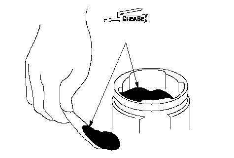 Use the grease included Use the grease includedin the inboard boot set. |
| 7. | Fit the inboard joint onto the driveshaft, and note these items:
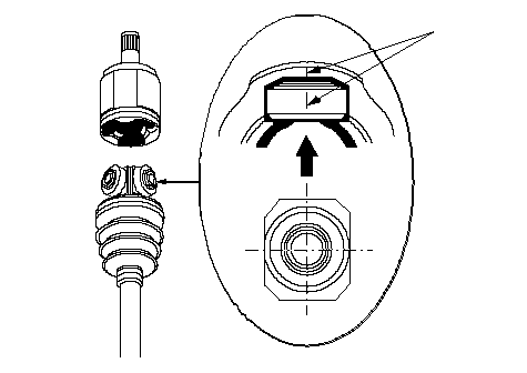 A A |
| 8. | Install the boot bands. |
| 9. | Install the new low profile band (A) onto the boot (B), then hook the tab (C) of the band.
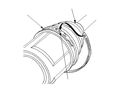 CAB CAB |
| 10. | Close the hook portion of the band with a commercially available boot band pincers (A), then hook the tabs (B) of the band.
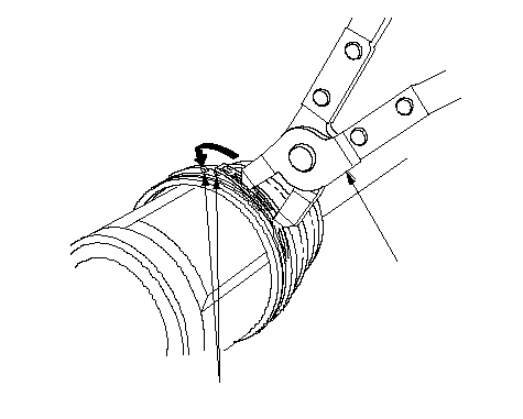 BA BA |
| 11. | Install the boot band on the other end of the boot, and repeat 9 through 10, then go to 21. |
| 12. | Fit the boot ends onto the driveshaft and the inboard joint, then install the new double loop band (A) onto the boot (B).
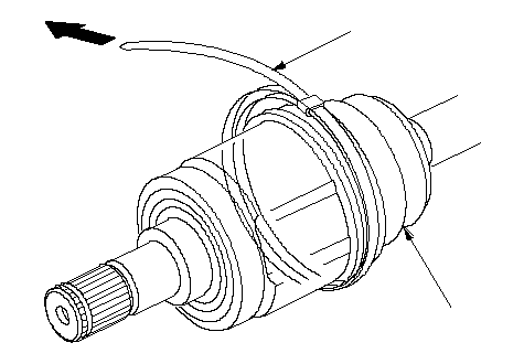 AB AB |
| 13. | Pull up the slack in the band by hand. |
| 14. | Mark a position (A) on the band 10-14 mm (0.4-0.6 in.) from the clip (B).
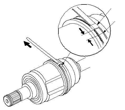 BA BA |
| 15. | Thread the free end of the band through the nose section of the commercially available boot band tool KD-3191 or equvialent (A), and into the slot on the winding mandrel (B).
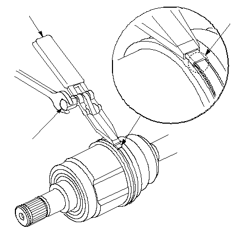 ABC ABC |
| 16. | Place a wrench on the winding mandrel of the boot band tool, and tighten the band until the marked spot (C) on the band meets the edge of the clip. |
| 17. | Lift up the boot band tool to bend the free end of the band 90 degrees to the clip. Center-punch the clip, then fold over the remaining tail onto the clip.
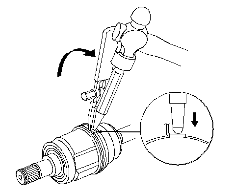 90 degrees 90 degrees |
| 18. | Unwind the boot band tool, and cut off the excess free end of the band to leave a 5-10 mm (0.2-0.4 in.) tail protruding from the clip.
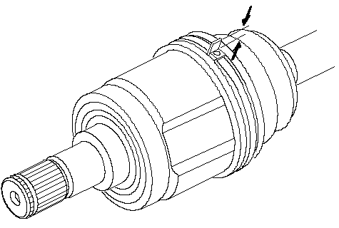 |
| 19. | Bend the band end (A) by tapping it down with a hammer. NOTE:
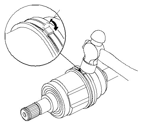 A A |
| 20. | Repeat steps 12 through 19 for the band on the other end of the boot. |
| 21. | Install the new set ring.
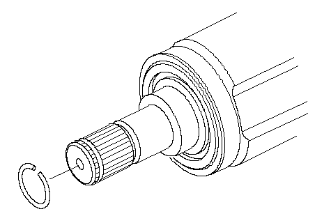 |
Outboard Joint Side
| 1. | Wrap the splines with vinyl tape (A) to prevent damage to the outboard boot.
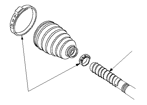 AB AB |
| 2. | Install the new ear clamp bands (B) and outboard boot, then remove the vinyl tape. Be careful not to damage the outboard boot. |
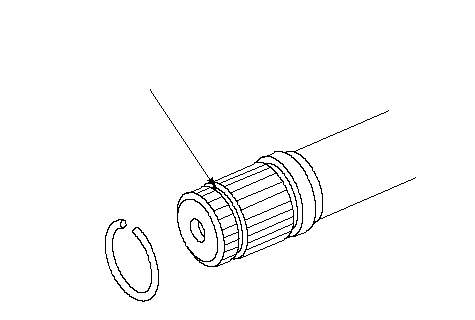
| 3. | Install the new stop ring into the driveshaft groove (A).
 A A |
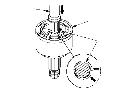
| 4. | Insert the driveshaft (A) into the outboard joint (B) until the stop ring (C) is close to the joint.
 CBAPush.Push. CBAPush.Push. |
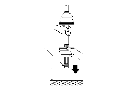
| 5. | To completely seat the outboard joint, pick up the driveshaft and joint, and drop them from about 10 cm (4 in.) onto a hard surface. Do not use a hammer as excessive force may damage the driveshaft. Be careful not to damage the threaded section (A) of the outboard joint.
 10cm 10cm(4 in.)A |
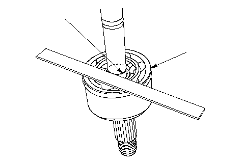
| 6. | Check the alignment of the paint mark (A) with the outboard joint end (B).
 AB AB |
| 7. | Pack the outboard joint (A) with the joint grease included in the new joint boot set.
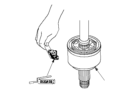 AUse the grease included AUse the grease includedin the outboard boot set. |
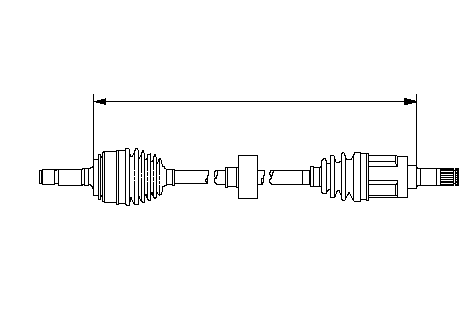
| 8. | Adjust the length of the driveshafts to the figure as shown, then adjust the boots to halfway between full compression and full extension. Make sure the ends of the boots seat in the grooves of the driveshaft and joint.
| |||||||||||||||
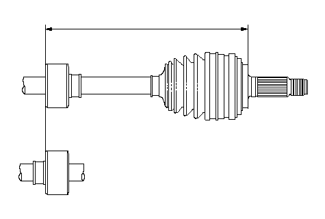
| 9. | Position the dynamic damper as shown.
| ||||||||||
| 10. | Fit the boot (A) ends onto the driveshaft (B) and outboard joint (C).
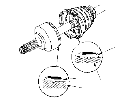 CABA CABA |
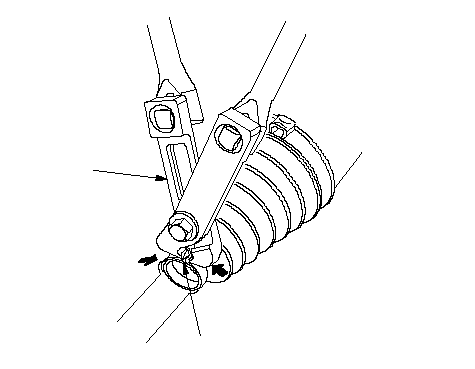
| 11. | Close the ear portion (A) of the band with a commercially available boot band pincers Kent-Moore J-35910 or equivalent (B).
 BA BA |
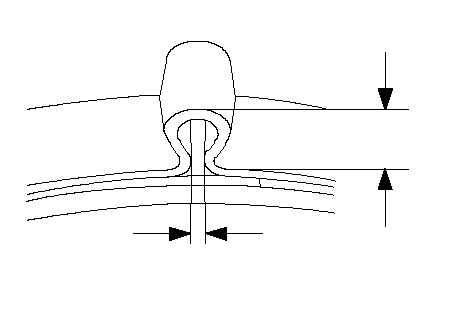
| 12. | Check the clearance between the closed ear portion of the bands. If the clearance is not within the standard, close the ear portion of the bands farther.
 6.0 mm (0.24 in.) MAX3.0 mm (0.12 in.) MAX 6.0 mm (0.24 in.) MAX3.0 mm (0.12 in.) MAX |