Intake Manifold Removal and Installation (Without ETCS)
Intake Manifold Removal and Installation
Exploded View
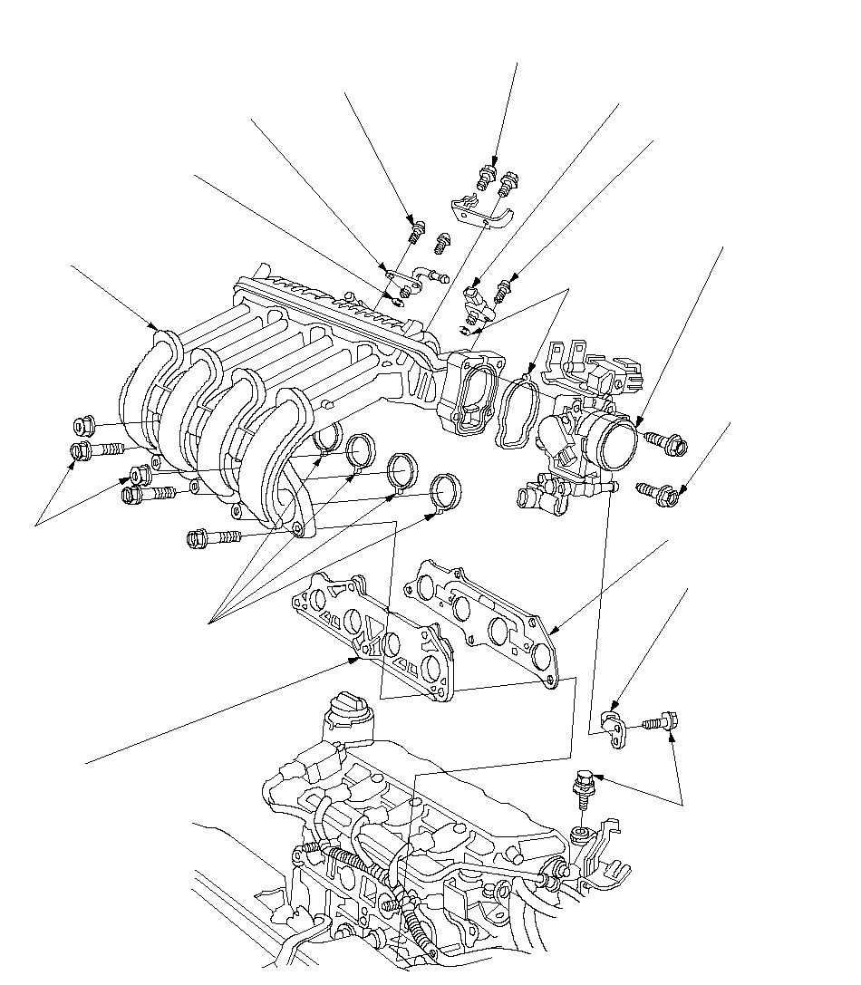 5 x 0.8 mm
6 N·m (0.6 kgf·m,
4 lbf·ft)INTAKE MANIFOLD
Replace if cracked or if
mating surface is damaged.O-RING
Replace.GASKET
Replace.THROTTLE BODYEXHAUST GAS
RECIRCULATION
(EGR) PLATEINTAKE MANIFOLD
BRACKET A8 x 1.25 mm
22 N·m
(2.2 kgf·m,
16 lbf·ft)O-RINGS
Replace.6 x 1.0 mm
12 N·m (1.2 kgf·m,
8.7 lbf·ft)BOOST PLATEMANIFOLD ABSOLUTE
PRESSURE (MAP) SENSOR5 x 0.8 mm
3.4 N·m (0.35 kgf·m,
2.5 lbf·ft)O-RINGS
Replace.6 x 1.0 mm
12 N·m (1.2 kgf·m,
8.7 lbf·ft)6 x 1.0 mm
12 N·m (1.2 kgf·m,
8.7 lbf·ft)
Removal:
| 1. | Remove the intake manifold cover. |
| 2. | Remove the air cleaner housing. |
| 3. | Remove the breather hose (A), brake booster vacuum hose (B) and Positive Crankcase Ventilation (PCV) hose (C).
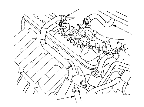 CBA CBA |
| 4. | Remove the throttle cable. |
| 5. | Remove the harness holder (A) and water bypass hose clamp (B).
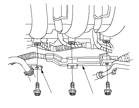 BA BA |
| 6. | Remove the Evaporative Emission (EVAP) canister hose. When Moving the Intake Manifold: 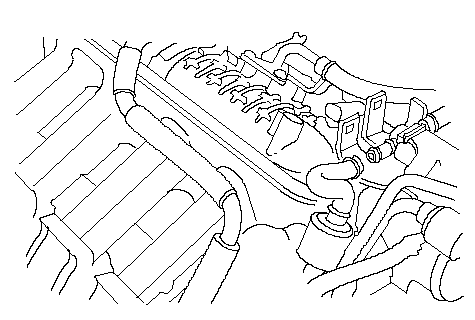 When Replacing the Intake Manifold: 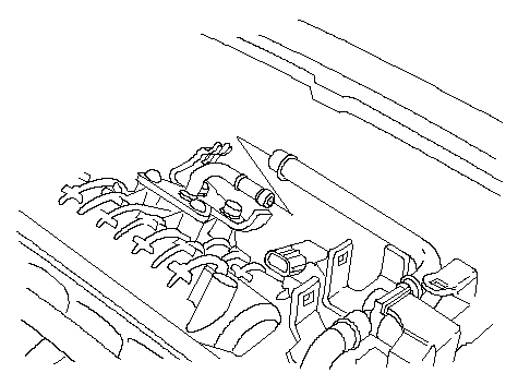 |
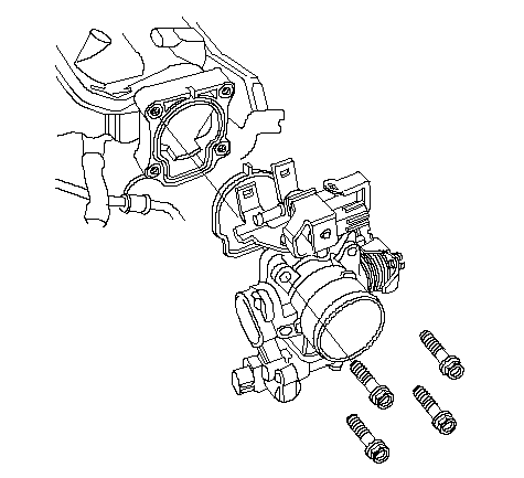
| 7. | When replacing the intake manifold, remove the throttle body.
 |
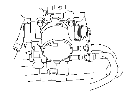
| 8. | If the engine coolant was drained, remove the water bypass hoses.
 |
| 9. | Remove the engine wire harness connectors and wire harness clamps from the intake manifold.
|
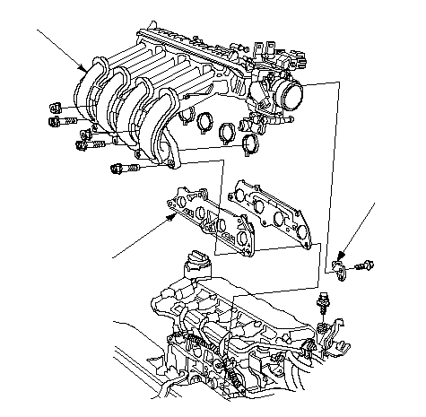
| 10. | Remove the intake manifold bracket A (A), then remove the intake manifold (B) and Exhaust Gas Recirculation (EGR) plate (C).
 BCA BCA |
Installation:
| 1. | Install the Exhaust Gas Recirculation (EGR) plate (A) with a new gasket (B).
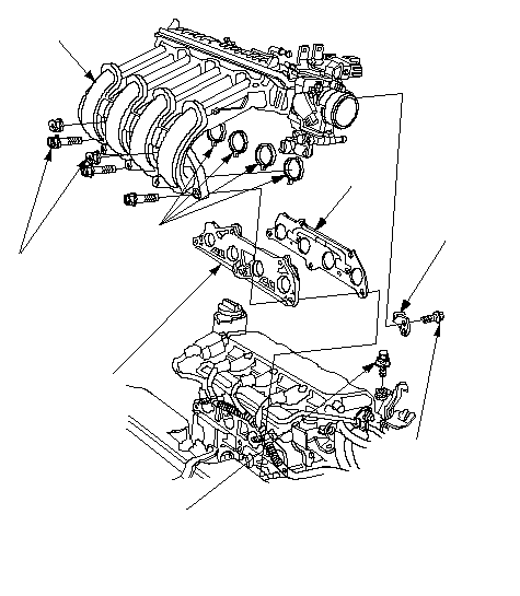 CAEBG CAEBG6 x 1.0 mm 12 N·m (1.2 kgf·m, 8.7 lbf·ft)F 6 x 1.0 mm 12 N·m (1.2 kgf·m, 8.7 lbf·ft)D8 x 1.25 mm 22 N·m (2.2 kgf·m, 16 lbf·ft) |
| 2. | Install the intake manifold (C) and tighten the bolts/nuts in a crisscross pattern in two or three steps, beginning with the inner bolt. Using the new O-rings (D). |
| 3. | Loosely install the intake manifold bracket A (E), and tighten the bolt (F) first, then the bolt (G). |
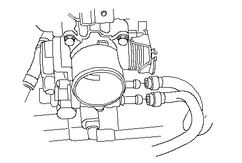
| 4. | Install the water bypass hoses, if it was removed.
 |
| 5. | Install the throttle body (A) with a new O-ring (B), if it was removed.
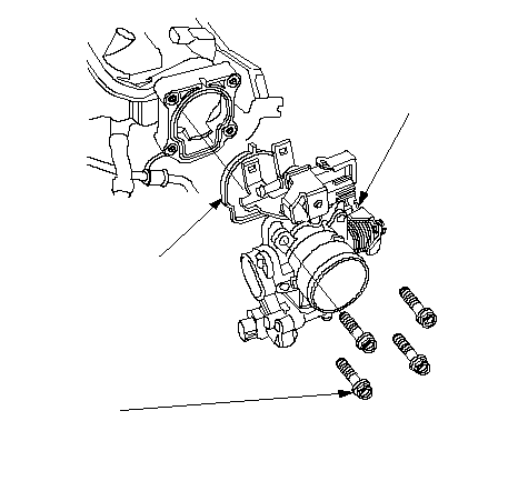 6 x 1.0 mm 6 x 1.0 mm12 N·m (1.2 kgf·m, 8.7 lbf·ft)BA |
| 6. | Install the Evaporative Emission (EVAP) canister hose. If Intake Manifold was Moved: 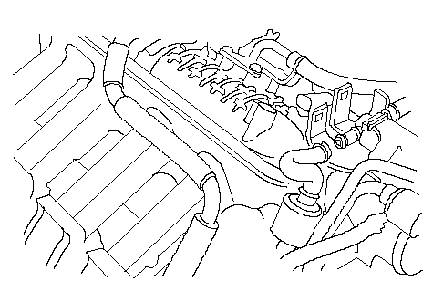 If Intake Manifold was Replaced: 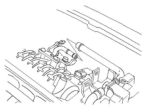 |
| 7. | Install the harness holder (A) and water bypass hose clamp (B).
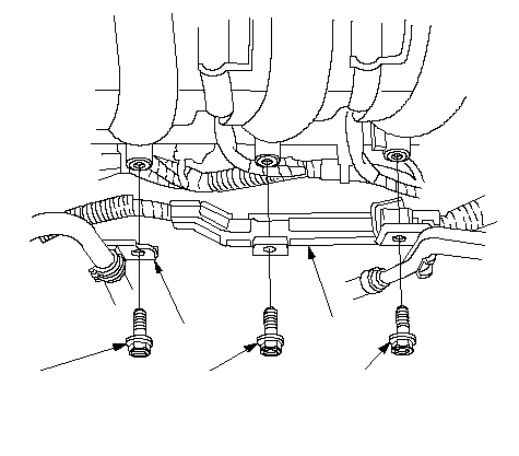 BA6 x 1.0 mm BA6 x 1.0 mm12 N·m (1.2 kgf·m, 8.7 lbf·ft)6 x 1.0 mm 9.8 N·m (1.0 kgf·m, 7.2 lbf·ft)6 x 1.0 mm 12 N·m (1.2 kgf·m, 8.7 lbf·ft) |
| 8. | Install the throttle cable, then adjust it. |
| 9. | Install the breather hose (A), brake booster vacuum hose (B) and Positive Crankcase Ventilation (PCV) hose (C).
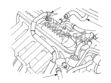 CBA CBA |
| 10. | Install the air cleaner housing. |
| 11. | Install the intake manifold cover. |
| 12. | After installation, check that all tubes, hoses and connectors are installed correctly. |
| 13. | If engine coolant drained, refill the radiator with engine coolant, and bleed air from the cooling system with the heater valve open. |