Manual Transmission Reassembly (5MT)
Manual Transmission Reassembly
NOTE: Prior to reassembling, clean all the parts in solvent, dry them, and apply lubricant to any contact surfaces.| 1. | Install the magnet (A) and differential assembly (B).
 BA BA |
| 2. | Install the 8 mm spring washer (A) and the 8 mm special bolt (B). |
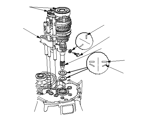
| 3. | Install the 36 mm spring washer (C) and 26 mm washer (D) over the ball bearing (E). Note the installation direction of the spring washer (C).
 GHAFDCB GHAFDCB31 N·m (3.2 kgf·m, 23 lbf·ft) |
| 4. | Tape the mainshaft splines (F) with vinyl tape to protect the seal. Install the mainshaft and countershaft (G) into the shift forks (H), and install them as an assembly. |
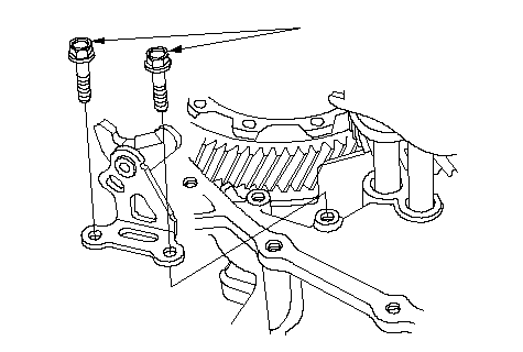
| 5. | Install the reverse lock cam.
 6 x 1.0 mm 6 x 1.0 mm15 N·m (1.5 kgf·m, 11 lbf·ft) |
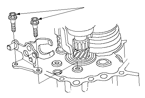
| 6. | Install the reverse shift fork.
 6 x 1.0 mm 6 x 1.0 mm15 N·m (1.5 kgf·m, 11 lbf·ft) |
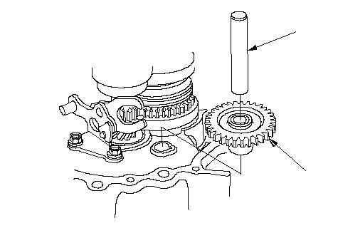
| 7. | Install the reverse idler gear (A) and reverse gear shaft (B).
 BA BA |
| 8. | Select the proper size 72 mm shim (A) according to the measurements made during the Mainshaft Thrust Clearance Adjustment (see page 13-52). Install the oil gutter plate (B), oil guide plate M, and 72 mm shim into the transmission housing (C). NOTE: Align the groove (D) of the transmission housing to the mark and finger (E) of oil guide plate M, and install it.
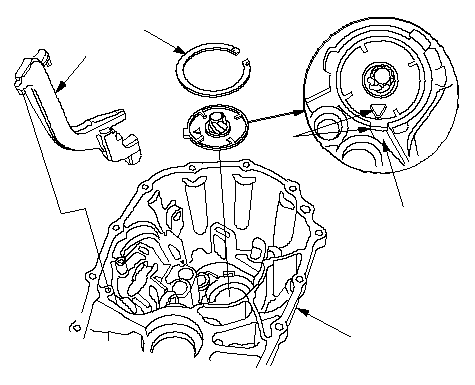 BAEDC BAEDC |
| 9. | Remove the dirt and oil from the transmission housing sealing surface. Apply liquid gasket (P/N 08C70-K0234M) to the sealing surface. Be sure to seal the entire circumference of the bolt holes to prevent oil leakage. NOTE: If 5 minutes have passed after applying liquid gasket, reapply it and assemble the housings. Allow it to cure at least 20 minutes after assembly before filling the transmission with oil.
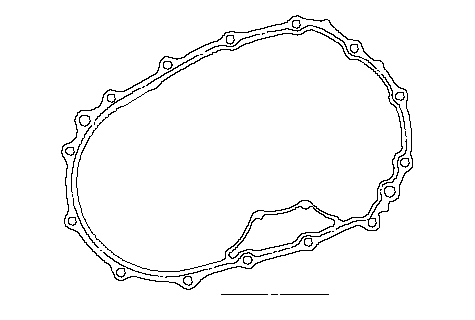 Liquid gasket Liquid gasket |
| 10. | Install the 14 x 20 mm dowel pins (A).
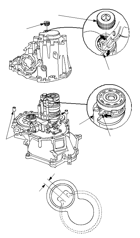 25 N·m 25 N·m(2.5 kgf·m, 18 lbf·ft)DBCA(1)E |
| 11. | Make the finger (B) of tapered cone ring touch the 5th shift fork (C) as shown. |
| 12. | Lower the transmission housing the rest of the way as you expand the 52 mm snap ring (D). Release the snap ring so it seats in the groove of the countershaft bearing. |
| 13. | Check that the 52 mm snap ring is securely seated in the groove of the countershaft bearing.
|
| 14. | Apply liquid gasket (P/N 08C70-K0234M) to the threads of the 32 mm sealing screw (E), and install it on the transmission housing. |
| 15. | Install the transmission hanger (A) and the 8 mm flange bolts finger-tight.
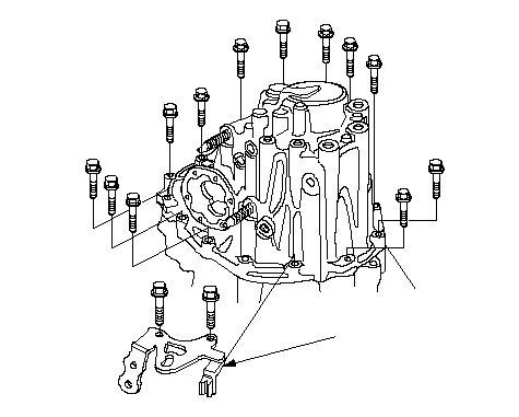 A A |
| 16. | Tighten the 8 mm flange bolts in a crisscross pattern in several steps.
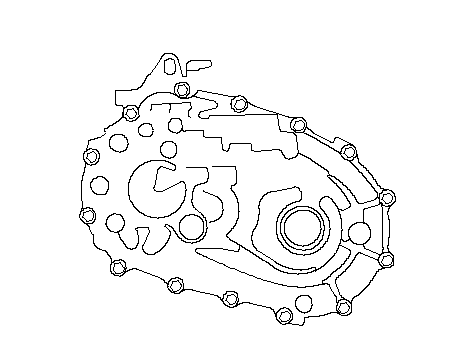 (1)(3)(7)(11)(13)(10)(6)(2)(4)(8)(12)(14)(9)(5)8 x 1.25 mm (1)(3)(7)(11)(13)(10)(6)(2)(4)(8)(12)(14)(9)(5)8 x 1.25 mm27 N·m (2.8 kgf·m, 20lbf·ft) |
| 17. | Remove the dirt and oil from the shift lever cover sealing surface. Apply liquid gasket (P/N 08C70-K0234M) to the sealing surface.
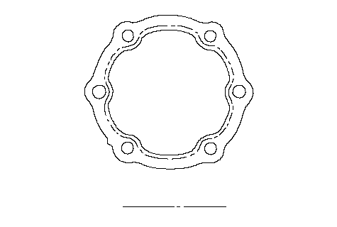 Liquid gasket Liquid gasket |
| 18. | Install the 8 x 10 mm dowel pins (A) and shift lever assembly (B).
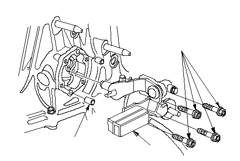 6 x 1.0 mm 6 x 1.0 mm12 N·m (1.2 kgf·m, 8.7 lbf·ft)AB |
| 19. | Install the set screws (A), new 12 mm washers, springs, and steel balls.
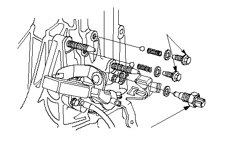 A A22 N·m (2.2 kgf·m, 16 lbf·ft)B 29 N·m (3.0 kgf·m, 22 lbf·ft) |
| 20. | Install the new washer and back-up light switch. |
| 21. | Install the new washer (A), drain plug (B), filler plug (C), new O-ring (D), and vehicle speed sensor (VSS) (E).
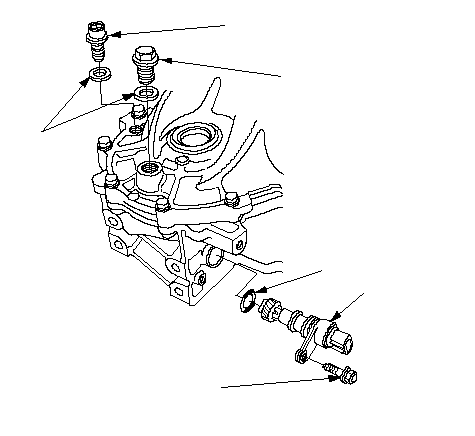 B B39 N·m (4.0 kgf·m, 29 lbf·ft)C 44 N·m (4.5 kgf·m, 33 lbf·ft)6 x 1.0 mm 9.8 N·m (1.0 kgf·m, 7.2 lbf·ft)EDA |