Service Precautions
Service Precautions
General
 |
| Observe all safety precautions and notes while working. |
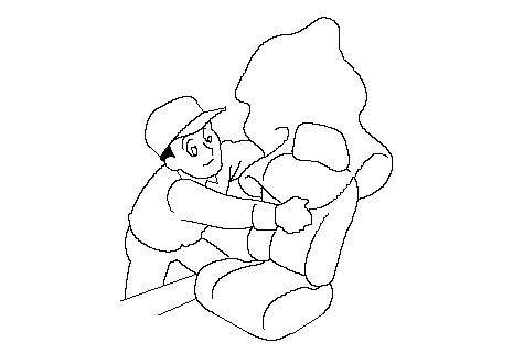
- Protect all painted surfaces and seats against dirt and scratches with a clean cloth or vinyl cover.
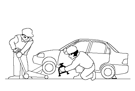
- Work safety and give your work your undivided attention. When either the front or rear wheels are to be raised, block the remaining wheels securely. Communicate at frequently as possible when work involves two or more workers. Do not run the engine unless the shop or working area is well ventilated.
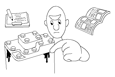
- Before removing or disassembling parts, they must be inspected carefully to isolate the cause for which service is necessary. Observe all safety notes and precautions and follow the proper procedures as described in this manual.
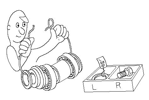
- Mark or place all removed parts in order in a parts rack so they can be reassembled in their original places.
- Use the special tool when use of such a tool is specified.
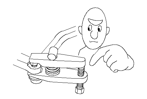
- Parts must be assembled with the proper torque according to the maintenance standards established.
- When tightening a series of bolts or nuts, begin with the center or large diameter bolts and tighten them in crisscross pattern in two or more steps.
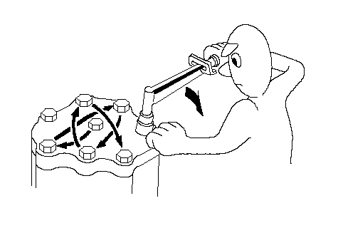
- Use new packings, gaskets, O-rings and cotter pins whenever reassembling.
- Do not reuse parts that must be required to replace. Always replace them.
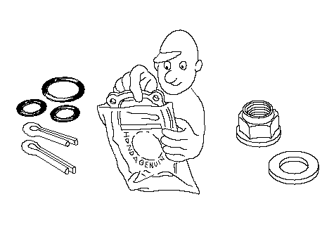
- Use genuine HONDA parts and lubricants or those equivalent. When parts are to be reused, they must be inspected carefully to make sure they are not damaged or deteriorated and are in good usable condition.
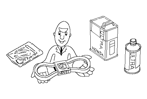
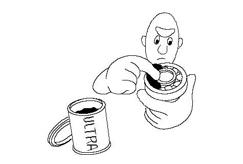
- Coat or fill parts with specified grease as specified. Clean all removed parts with solvent upon disassembly.
- Brake fluid and hydraulic components
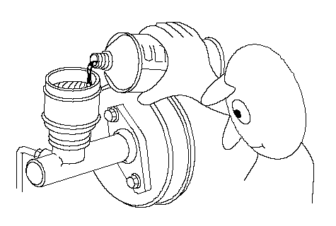
- When replenishing the system, use extreme care to prevent dust and dirt from entering the system.
- Do not mix different brands of fluid as they may not be compatible.
- Do not reuse drained brake fluid.
- Because brake fluid can cause damage to painted and resin surfaces, care should be taken not to spill it on such materials. If spilled accidentally, quickly rinse it with water or warm water from painted or resin surfaces.
- After disconnecting brake hoses or pipes, be sure to plug the openings to prevent loss of brake fluid.
- Clean all disassembled parts only in clean BRAKE FLUID. Blow open all holes and passages with compressed air.
- Keep disassembled parts from air-borne dust and abrasives.
- Check that parts are clean before assembly.
- When replenishing the system, use extreme care to prevent dust and dirt from entering the system.
- Avoid oil or grease getting on rubber parts and tubes, unless specified.
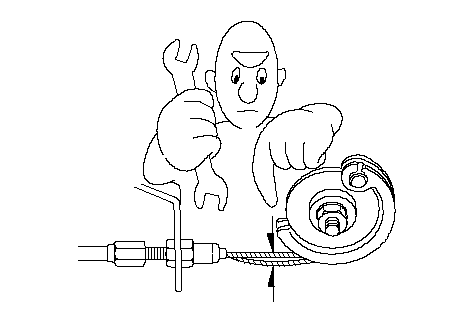
- Upon assembling, check every part for proper installation and operation.
Electrical Troubleshooting Information
Before Troubleshooting
| 1. | Check applicable fuses in the appropriate fuse/relay box. |
| 2. | Check the battery for damage, state of charge, and clean and tighten the connections.
|

| 3. | Check the alternator belt tension. |
Handling Connectors
- Make sure the connectors are clean and have no loose wire terminals.
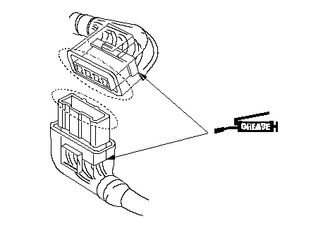
- Make sure multiple cavity connectors are packed with grease (except watertight connectors).
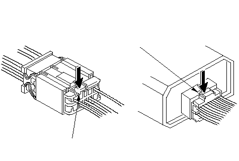
- All connectors have push-down release type locks (A).
 AA
AA- Some connectors have a clip on their side used to attach them to a mounting bracket on the body or on another component. This clip has a pull type lock.
- Some mounted connectors cannot be disconnected unless you first release the lock and remove the connector from its mount bracket (A).
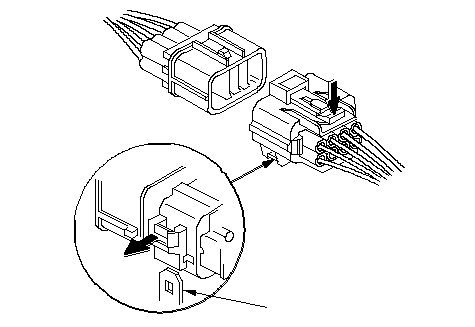 A(2)(1)
- Never try to disconnect connectors by pulling on their wires; pull on the connector halves instead.
- Always reinstall plastic covers.
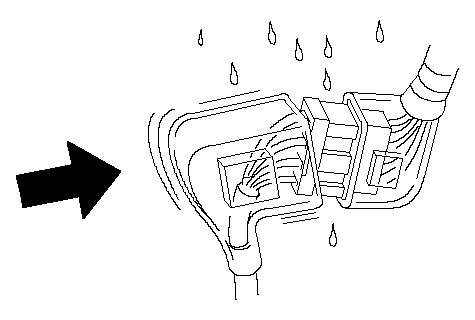
- Before connecting connectors, make sure the terminals (A) are in place and not bent.
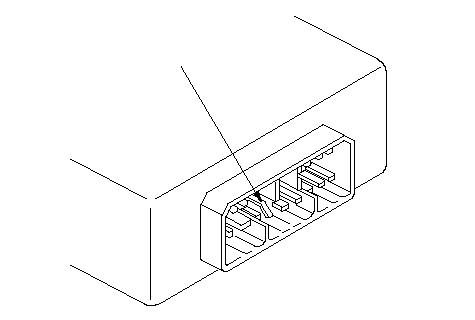 A
A- Check for loose retainer (A) and rubber seals (B).
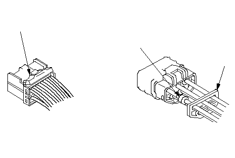 ABA
ABA- The backs of some connectors are packed with grease. Add grease if necessary. If the grease is contaminated, replace it.
- Insert the connector all the way and make sure it is securely locked.
- Position wires so that the open end of the cover faces down.
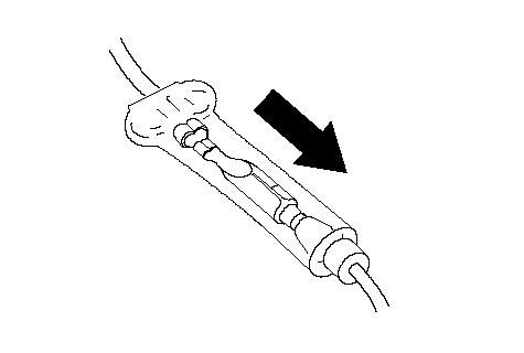 DOWN
DOWNHandling Wires and Harnesses
- Secure wires and wire harnesses to the frame with their respective wire ties at the designated locations.
- Remove clips carefully; don't damage their locks (A).
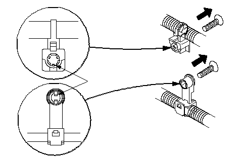 A
A- Slip pliers (A) under the clip base and through the hole at an angle, then squeeze the expansion tabs to release the clip.
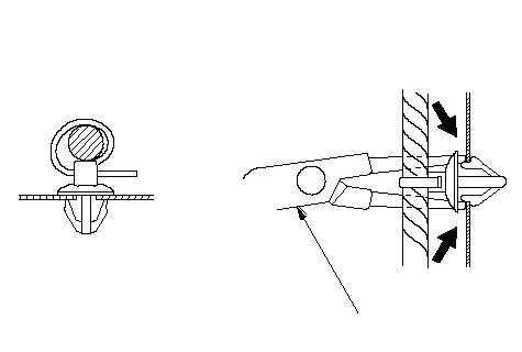 A
A- After installing harness clips, make sure the harness doesn't interfere with any moving parts.
- Keep wire harnesses away from exhaust pipes and other hot parts, from sharp edges of brackets and holes, and from exposed screws and bolts.
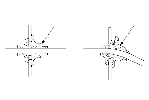
- Seat grommets in their grooves properly (A). Do not leave grommets distorted (B).
 AB
ABTesting and Repairs
- Do not use wires or harnesses with broken insulation. Replace them or repair them by wrapping the break with electrical tape.
- After installing parts, make sure that no wires are pinched under them.
- When using electrical test equipment, follow the manufacturer's instructions and those described in this manual.
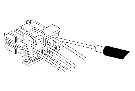
- If possible, insert the probe of the tester from the wire side (except waterproof connector).
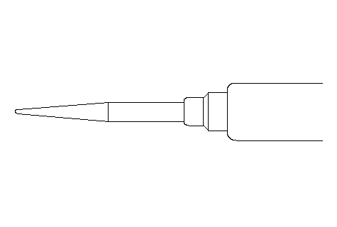
- Use a probe with a tapered tip.
- Refer to the instructions in the Honda Terminal Kit for identification and replacement of connector terminals.
When checking any control module(s) or unit(s) connector terminals, gently slide the sharp tester probe from the wire side into the connector until it comes in contact with the terminal end of the wire.
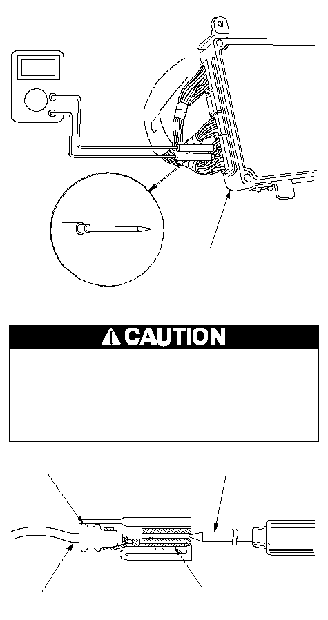 ··Puncturing the insulation on a wire can cause poor
or intermittent electrical connections.For testing at connectors, bring the tester probe into
contact with the terminal from the connector side of
wire harness connectors in the engine compartment.
For female connectors, just touch lightly with
the tester probe and do not insert the probe.DIGITAL CIRCUIT TESTER
(Commercially available) or
07411-0020000CONTROL MODULE or
CONTROL UNITSHARP TESTER PROBEWIRE HARNESSRUBBER SEALTERMINALTESTER PROBE
Five-step Troubleshooting
| 1. | Verify The Complaint Turn on all the components in the problem circuit to verify the customer complaint. Note the symptoms. Do not begin disassembly or testing until you have narrowed down the problem area. |
| 2. | Analyze The Schematic Look up the schematic for the problem circuit. Determine how the circuit is supposed to work by tracing the current paths from the power feed through the circuit components to ground. If several circuits fail at the same time, the fuse or ground is a likely cause. Based on the symptoms and your understanding of the circuit operation, identify one or more possible causes of the problem. |
| 3. | Isolate The Problem By Testing The Circuit Make circuit tests to check the diagnosis you made in step 2. Keep in mind that a logical, simple procedure is the key to efficient troubleshooting. Test for the most likely cause of failure first. Try to make tests at points that are easily accessible. |
| 4. | Fix The Problem Once the specific problem is identified, make the repair. Be sure to use proper tools and safe procedures. |
| 5. | Make Sure The Circuit Works Turn on all components in the repaired circuit in all modes to make sure you¢ve fixed the entire problem. If the problem was a blown fuse, be sure to test all of the circuits on the fuse. Make sure no new problems turn up and the original problem does not recur. |
Wire Color Codes
The following abbreviations are used to identify wire colors in the circuit schematics:
| WHT. | White |
| YEL. | Yellow |
| BLK. | Black |
| BLU. | Blue |
| GRN. | Green |
| RED. | Red |
| ORN. | Orange |
| PNK. | Pink |
| BRN. | Brown |
| GRY. | Gray |
| PUR. | Purple |
| LT BLU. | Light Blue |
| LT GRN. | Light Green |
The wire insulation has one color or one color with another color stripe. The second color is the stripe.
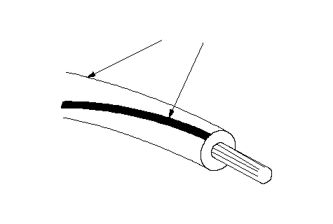 WHT/BLK