Fuel Gauge Sending Unit Test
NOTE: For the fuel gauge system circuit diagram,
refer to the Gauges Circuit Diagram.| 1. | Check the No. 16 (7.5A) fuse in the under-dash fuse/relay box before testing.
|
| 2. | Turn the ignition switch OFF.
|
| 4. | Disconnect the fuel pump 5P connector.
|
| 5. | Measure voltage between the fuel pump 5P connector terminals No. 1 and No. 2 with the ignition switch ON (II). There should be between 5 and 8 V.
- If the voltage is as specified, go to 6.
- If the voltage is not as specified, check for:
- an open in the YEL/BLK or BLK wire.
- poor ground (G 402).
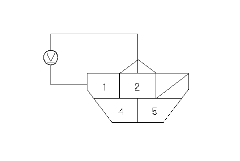 Wire side of female terminalsFUEL PUMP 5P CONNECTOR(YEL/GRN)(BLK) Wire side of female terminalsFUEL PUMP 5P CONNECTOR(YEL/GRN)(BLK) |
| 6. | Turn the ignition switch OFF.
|
| 7. | Install a 2W resistor between the fuel pump 5P connector terminals No. 1 and No. 2, then turn the ignition switch ON (II).
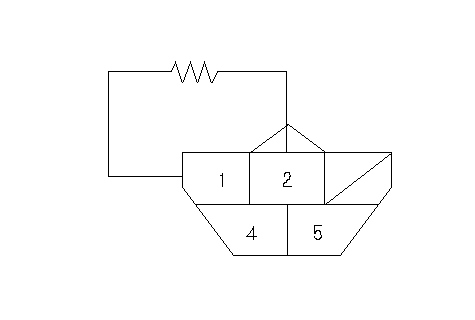 Wire side of female terminalsFUEL PUMP 5P CONNECTOR(YEL/GRN)(BLK)2W RESISTOR Wire side of female terminalsFUEL PUMP 5P CONNECTOR(YEL/GRN)(BLK)2W RESISTOR |
| 8. | Check that the pointer of the fuel gauge indicates ‘‘F''.
- If the pointer of the fuel gauge does not indicates ‘‘F'', replace the gauge.
- If the gauge is OK, inspect the fuel gauge sending unit.
NOTE: The pointer of the fuel gauge returns to the bottom on the gauge dial when the ignition switch is OFF regardless of the fuel level.
|
| 10. | Measure the resistance between the No. 1 and No. 2 terminals with the float at E (EMPTY), 1/2 (HALF FULL), and F (FULL) positions.
If you do not get the following readings, replace the fuel gauge sending unit.
| Float Position | F | 1/2 | LOW | E | | Resistance (W) | 11
-13 | 68.5
-74.5 | 112.1- 125.4 | 130
-132 |
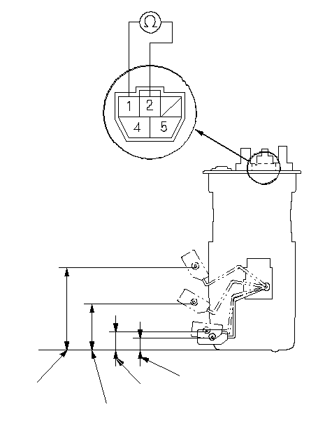 Terminal side of Terminal side of
male terminalsF1/2LOWE |