Power Relays Test
Power Relays Test
Use this chart to identify the type of relay, then do the test listed for it.NOTE: See page 22-102 for the turn signal/hazard flasher control circuit input test.
| Relay | Test |
|---|---|
| A/C compressor clutch relay | Normally-open type A |
| A/T reverse relay | |
| Blower motor relay | |
| Condensor fan relay | |
| Headlight relay | |
| Horn relay | |
| PGM-FI main relay 1 | |
| PGM-FI main relay 2 | |
| Power mirror defogger relay | |
| Power window relay | |
| Radiator fan relay | |
| Starter cut relay | |
| Taillight relay | |
| EPS motor relay | Normally-open type B |
| Power door lock/fuel lid lock relay | Five terminal type |
| Power door unlock/fuel lid unlock relay | |
| Sunroof open relay | |
| Sunroof close relay | |
| Left super locking relay | |
| Right super locking relay |
Normally-open type A:
Check for continuity between the terminals.
- There should be continuity between the No. 1 and No. 2 terminals when power and ground are connected to the No. 3 and No. 4 terminals.
- There should be no continuity between the No. 1 and No. 2 terminals when power is disconnected.
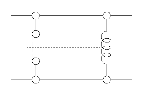 2314
2314type 1:
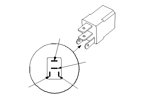 1234
1234type 2:
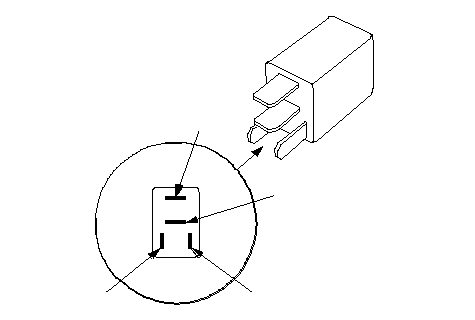 1243
1243· PGM-FI main relay 1
· PGM-FI main relay 2
type 1:
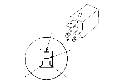 1243
1243type 2:
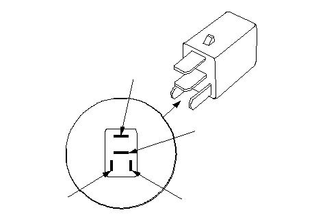 1243
1243Normally-open type B:
Check for continuity between the terminals.
- There should be continuity between the No. 1 and No. 3 terminals when power and ground are connected to the No. 2 and No. 4 terminals.
- There should be no continuity between the No. 1 and No. 3 terminals when power is disconnected.
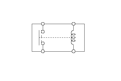 1234
1234
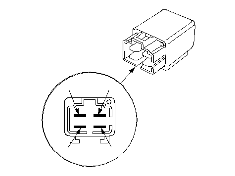 1234
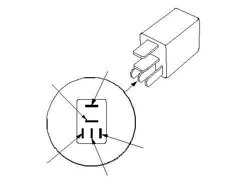
1234Five terminal type
Check for continuity between the terminals.
- There should be continuity between the No. 1 and No. 2 terminals when power and ground are connected to the No. 3 and No. 5 terminals.
- There should be continuity between the No. 1 and No. 4 terminals when power is disconnected.
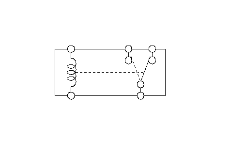 12345
12345
 21345
21345