A/T Gear Position Indicator Input Test - Without 7-speed Mode (CVT)
A/T Gear Position Indicator Input Test - Without 7-speed Mode
| 1. | If the [D] indicator or MIL has been reported on, check for a DTC, and repair the system as indicated by DTC. |
| 2. | If the [D] indicator does not come on, and the A/T gear position indicator does not come on, remove the gauge assembly from the dashboard, then disconnect the gauge assembly connectors A (20P) and B (14P). |
| 3. | Inspect the connectors and connector terminals to be sure they are making good contact. |
| 4. | If the terminals are bent, loose, or corroded, repair them as necessary, and recheck the system. |
| 5. | Shift to [P] position, and check for continuity between B14 terminal (BLU/BLK) and ground. There should be continuity in [P] position and no continuity in any other shift lever position. If the test results are different, check for faulty transmission range switch or open in the wire.
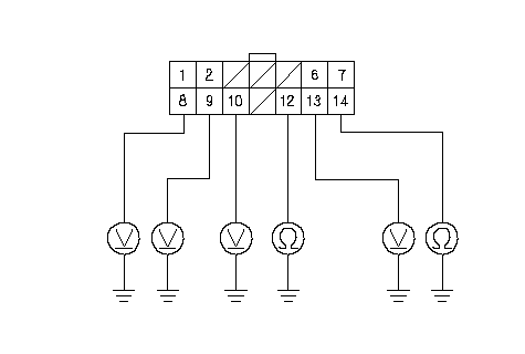 ATP S ATP S(BLU/WHT)ATP P (BLU/BLK)D IND (PNK)ATP L (BLU)ATP N (RED/BLK)ATP R (WHT)Wire side of female terminalsGAUGE ASSEMBLY CONNECTOR B (14P) |
| 6. | Turn the ignition switch ON (II), and shift to [R] position with pressing the brake pedal. Check for voltage between B13 terminal (WHT) and ground. There should be 0 V in [R] position, and about 10 V in any other position. If the test results are different, check for a faulty transmission range switch or an open in the wire. |
| 7. | Shift to [N] position, and check for continuity between B12 terminal (RED/BLK) and ground. There should be continuity in [N] position and no continuity in any other position. If the test results are different, check for faulty transmission range switch or open in the wire. |
| 8. | Shift to [D] position, and check for voltage between B9 terminal (PNK) and ground. There should be battery voltage in [D] position, and 0 V in any other position. If the test results are different, check for faulty transmission range switch and PCM, or an open in the wire. |
| 9. | Shift to [S] position, and check for voltage between B8 terminal (BLU/WHT) and ground. There should be 0 V in [S] position, and about 10 V in any other position. If the test results are different, check for a faulty transmission range switch or an open in the wire. |
| 10. | Shift to [L] position, and check for voltage between B10 terminal (BLU) and ground. There should be 0 V in [L] position, and about 10 V in any other position. If the test results are different, check for a faulty transmission range switch or an open in the wire. |
| 11. | Check for voltage between A2 terminal (YEL) and ground. There should be battery voltage. If the test result is different, check for a blown No. 16 (7.5A) fuse in the under-dash fuse/relay box or an open in the wire.
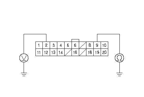 Wire side of female terminalsGAUGE ASSEMBLY CONNECTOR A (20P)IG1 (YEL)GND (BLK) Wire side of female terminalsGAUGE ASSEMBLY CONNECTOR A (20P)IG1 (YEL)GND (BLK) |
| 12. | Check for continuity between A9 terminal (BLK) and ground. There should be continuity under all conditions. If the test result is different, check for a poor ground (G501) or an open in the wire. |
| 13. | If a input test prove OK, but the indicator is faulty, replace the gauge assembly. |