DTC Troubleshooting: 15-1
DTC Troubleshooting: 15-1
| DTC 15-1: | Faulty OPDS Unit |
| 1. | Make sure nothing is on the front passenger's seat. |
| 2. | Initialize the OPDS unit. |
| 3. | Erase the DTC memory. |
| 4. | Read the DTC. Is DTC 15-1 indicated? YES - Go to 5. NO - Intermittent failure, system is OK at this time. Go to Troubleshooting Intermittent Failures. |
| 5. | Check the No. 9 (15A) fuse in the under-dash fuse/relay box. Is the fuse OK? YES - Go to 6. NO - Go to 9. |
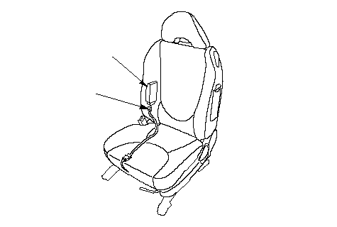
| 6. | Disconnect the O1o connector (A) from the OPDS unit (B).
 BA BA |
| 7. | Turn the ignition switch ON (II). |
| 8. | Check for voltage between the No. 4 terminal of the O1o connector and body ground. There should be battery voltage.
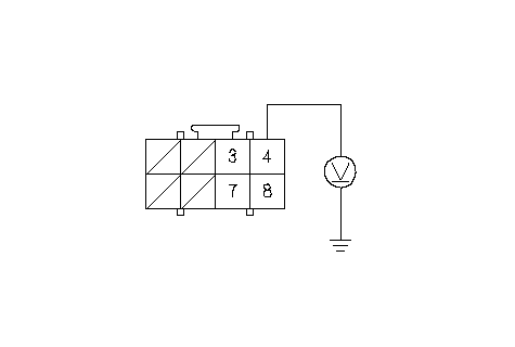 Wire side of female terminalsO1o CONNECTOR Wire side of female terminalsO1o CONNECTOR Is there battery voltage? YES - Go to 16. NO - Open in the floor wire harness or in the OPDS unit harness; replace the faulty harness.n |
| 9. | Replace the No. 9 (15A) fuse in the under-dash fuse/relay box. |
| 10. | Turn the ignition switch ON (II) for 30 seconds, then turn it OFF. |
| 11. | Check the No. 9 (15A) fuse in under-dash fuse/relay box. Is the fuse OK? YES - Intermittent failure, system is OK at this time. Go to Troubleshooting Intermittent Failures. NO - Go to 12. |
| 12. | Replace the No. 9 (15A) fuse in the under-dash fuse/relay box. |
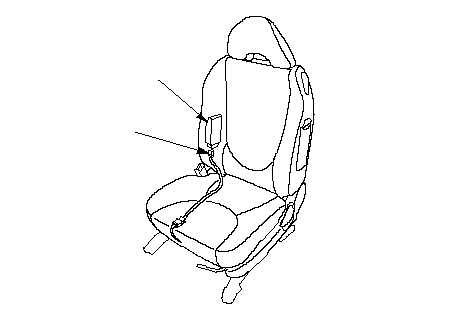
| 13. | Disconnect the O1o connector (A) from the OPDS unit (B).
 BA BA |
| 14. | Turn the ignition switch ON (II) for 30 seconds, then turn it off. |
| 15. | Check the No. 9 (15A) fuse in the under-dash fuse/relay box. Is the fuse OK? YES - Short to ground in the OPDS unit; replace the OPDS unit.n NO - Short to ground in the No. 9 (15A) circuit.n |
| 16. | Turn the ignition switch OFF. |
| 17. | Check resistance between the No. 8 terminal of the O1o connector and body ground. There should be 0-1.0 W.
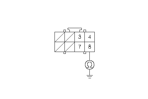 O1o CONNECTORWire side of female terminals O1o CONNECTORWire side of female terminalsIs the resistance as specified? YES - Go to 18. NO - Open in floor wire harness or OPDS unit harness, or poor ground (G501). If the G501 is OK, replace the faulty harness.n |
| 18. | Disconnect the battery negative cable, and wait for 3 minutes. |
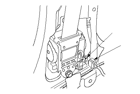
| 19. | Disconnect the TL1o and TR1o connectors (A) from the TL1i and TR1i connectors (B).
 AB AB |
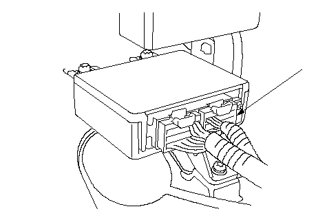
| 20. | Disconnect the U2o connector (A) from the SRS unit.
 A A |
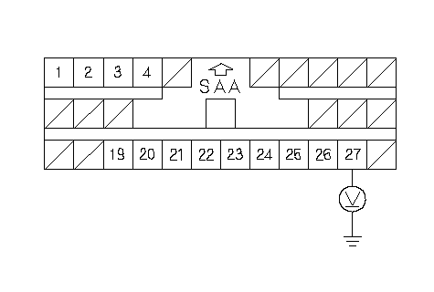
| 21. | Check resistance between the No. 27 terminal of the U2o connector and body ground. There should be 1 MW or more.
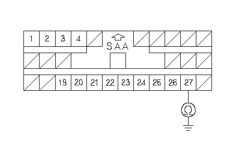 U2o CONNECTORWire side of female terminals U2o CONNECTORWire side of female terminalsIs the resistance as specified? YES - Go to 22. NO - Short to ground in the floor wire harness or OPDS unit harness; replace the faulty harness.n |
| 22. | Check resistance between the No. 27 terminal of the U2o connector and the No. 7 terminal of the O1o connector. There should be 1.0 W or less.
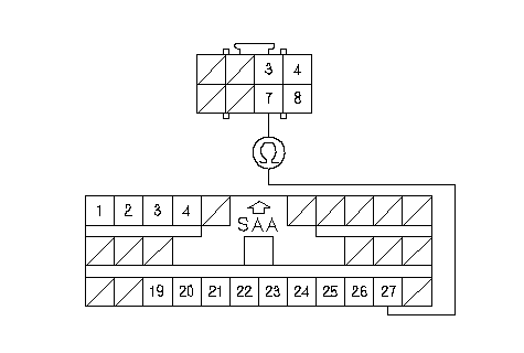 O1o CONNECTORWire side of female terminalsU2o CONNECTORBLUGRN/ORN O1o CONNECTORWire side of female terminalsU2o CONNECTORBLUGRN/ORNIs the resistance as specified? YES - Go to 23. NO - Open in the floor wire harness or in the OPDS unit harness; replace the faulty harness.n |
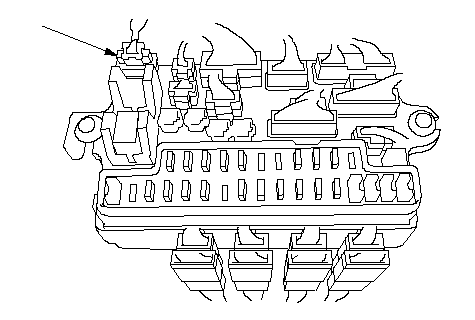
| 23. | Disconnect the F1o connector (A) from the under-dash fuse/relay box.
 A A |
| 24. | Reconnect the negative battery cable. |
| 25. | Turn the ignition switch ON (II). |
| 26. | Check for voltage between the No. 3 terminal of the U2o connector and body ground. There should be 0.5 V or less.
 U2o CONNECTORWire side of female terminals U2o CONNECTORWire side of female terminalsIs the voltage as specified? YES - Faulty OPDS unit or SRS unit. Replace the OPDS unit. If the problem is still present, replace the SRS unit.n NO - Short to power in the floor wire harness or in the OPDS unit harness; replace the faulty harness.n |