Manual Transmission Installation (5MT)
Manual Transmission Installation
| 1. | Check the two dowel pins are installed in the clutch housing. |
| 2. | Apply Urea Grease UM264 (P/N 41211-PY5-305) to the release fork (A) and the release bearing (B). Install the release fork and the release bearing.
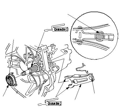 0.3-0.9 g 0.3-0.9 g(0.01-0.03 oz)0.5-1.1 g (0.02-0.04 oz)0.4-1.0 g (0.01-0.04 oz)AB |
| 3. | Place the transmission on the transmission jack, and raise it to the engine level. |
| 4. | Install the lower transmission mounting bolts.
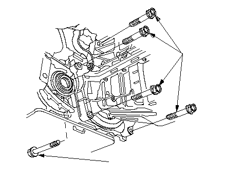 12 x 1.25 mm 12 x 1.25 mm64 N·m (6.5 kgf·m, 47 lbf·ft)12 x 1.25 mm 64 N·m (6.5 kgf·m, 47 lbf·ft) |
| 5. | Install the air cleaner stay.
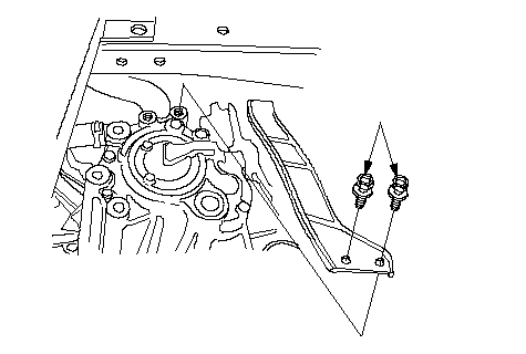 8 x 1.25 mm 8 x 1.25 mm22 N·m (2.2 kgf·m, 16 lbf·ft) |
| 6. | Install the front transmission mount.
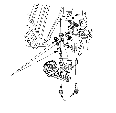 10 x 1.25 mm 10 x 1.25 mm39 N·m (4.0 kgf·m, 29 lbf·ft)10 x 1.25 mm 39 N·m (4.0 kgf·m, 29 lbf·ft) |
| 7. | Install the clutch cover.
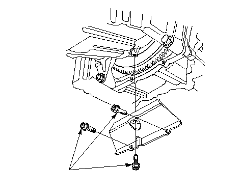 6 x 1.0 mm 6 x 1.0 mm12 N·m (1.2 kgf·m, 9 lbf·ft) |
| 8. | Install the rear transmission mount bracket (A) and the rear transmission mount (B).
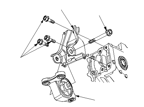 10 x 1.25 mm 10 x 1.25 mm44 N·m (4.5 kgf·m, 33 lbf·ft)12 x 1.25 mm 59 N·m (6.0 kgf·m, 43 lbf·ft)BA |
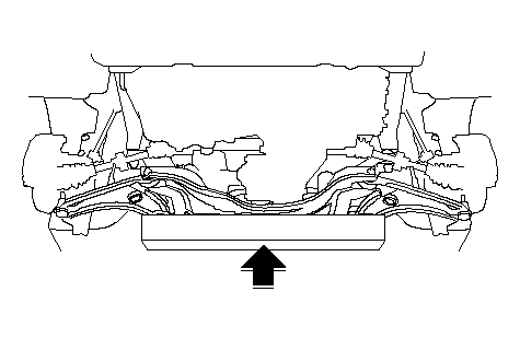
| 9. | Support the sub-frame with a 4 x 4 x 40 in. piece of wood and a jack.
 |
| 10. | Install the front sub-frame (A) and the new front sub-frame mounting bolts (B).
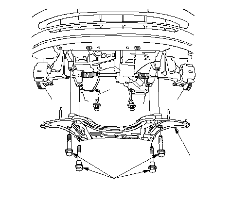 B B14 x 1.5 mm 93 N·m (9.5 kgf·m, 69 lbf·ft)A |
| 11. | Install the three rear transmission mount bracket bolts.
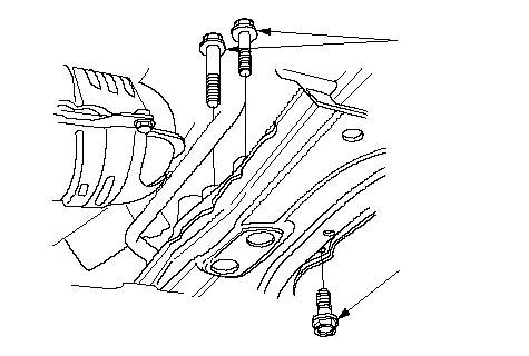 10 x 1.25 mm 10 x 1.25 mm44 N·m (4.5 kgf·m, 33 lbf·ft)10 x 1.25 mm 44 N·m (4.5 kgf·m, 33 lbf·ft) |
| 12. | Install the two power steering gearbox bracket bolts.
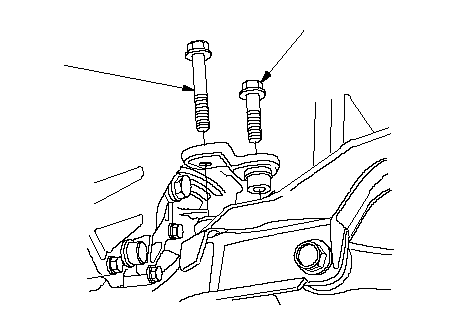 10 x 1.25 mm 10 x 1.25 mm39 N·m (4.0 kgf·m, 29 lbf·ft)10 x 1.25 mm 49 N·m (5.0 kgf·m, 36 lbf·ft) |
| 13. | Install the two power steering gearbox bracket bolts.
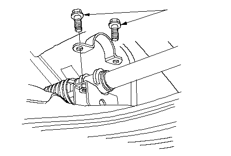 10 x 1.25 mm 10 x 1.25 mm44 N·m (4.5 kgf·m, 33 lbf·ft) |
| 14. | Install the two sub-frame stay bolts.
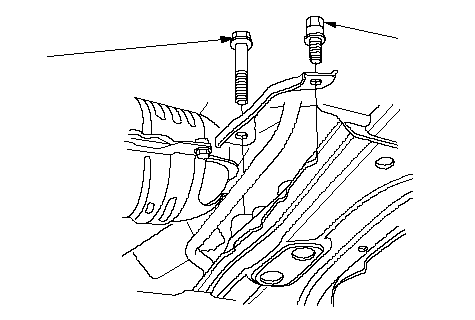 10 x 1.25 mm 10 x 1.25 mm39 N·m (4.0 kgf·m, 29 lbf·ft)10 x 1.25 mm 49 N·m (5.0 kgf·m, 36 lbf·ft) |
| 15. | Install the driveshafts. |
| 16. | Install the heat cover (A) and the bolts (B). NOTE: Tighten the three bolts in number of the order.
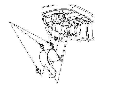 6 x 1.0 mm 6 x 1.0 mm9.8 N·m (1.0 kgf·m, 7.2 lbf·ft)(1)(2)(3) |
| 17. | Install the ball joints (A), nuts (B) and the new cotter pins (C). |
| 18. | Connect the lower arms (D), and install castle nuts (E) and the spring clips (F). |
| 19. | Connect the ball joint pins (G) to the stabilizers (H), and install the nuts (I). Insert a 5 mm Allen wrench (J) in the top of the ball joint pins, and tighten the nuts.
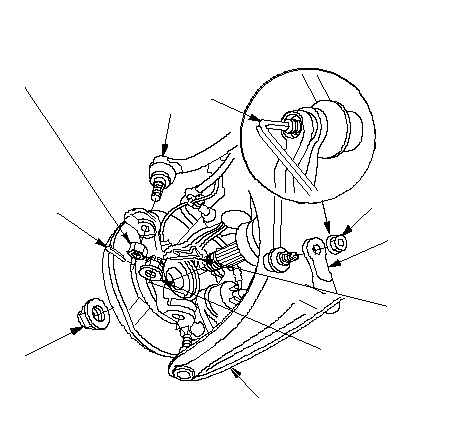 K K22 x 1.5 mm 181 N·m (18.5 kgf·m, 134 lbf·ft)DE 12 x 1.25 mm 49-59 N·m (5.0-6.0 kgf·m, 36-43 lbf·ft)FHICAJB 10 x 1.25 mm 43 N·m (4.4 kgf·m, 32 lbf·ft)G 10 x 1.25 mm 29 N·m (3.0 kgf·m, 22 lbf·ft) |
| 20. | Install the new spindle nuts (K). |
| 21. | Install the splash shield.
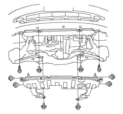 |
| 22. | Install the transmission mount bracket.
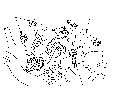 10 x 1.25 mm 10 x 1.25 mm39 N·m (4.0 kgf·m, 29 lbf·ft)10 x 1.25 mm 44 N·m (4.5 kgf·m, 33 lbf·ft)10 x 1.25 mm 39 N·m (4.0 kgf·m, 29 lbf·ft) |
| 23. | Install the one upper transmission mounting bolt.
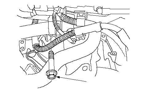 12 x 1.25 mm 12 x 1.25 mm64 N·m (6.5 kgf·m, 47 lbf·ft) |
| 24. | Remove the chain hoist and engine hanger from the engine. |
| 25. | Connect the vehicle speed sensor (VSS) connector (A), then install the oxygen sensor clip (B).
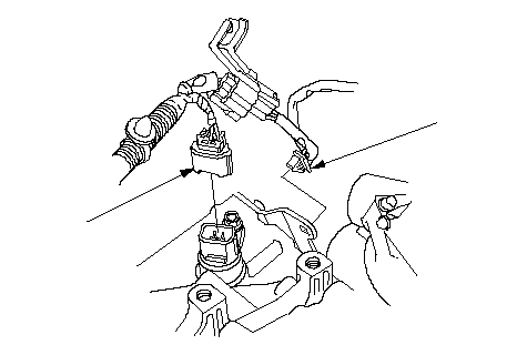 AB AB |
| 26. | Install the cable bracket (A) and cables (B).
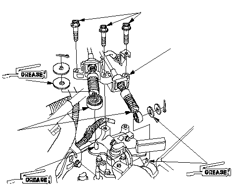 AB8 x 1.25 mm AB8 x 1.25 mm27 N·m (2.8 kgf·m, 20 lbf·ft) |
| 27. | Connect the back-up light switch connector (A), then install the harness clips (B).
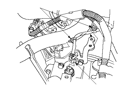 BA BA |
| 28. | Install the boot (A).
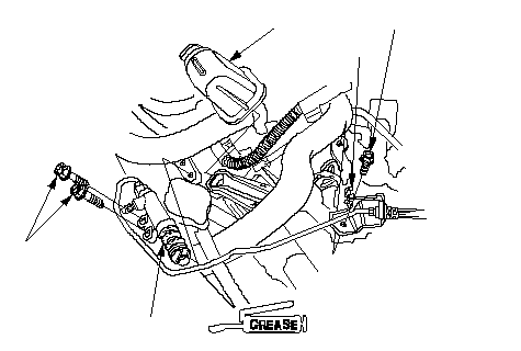 8 x 1.25 mm 8 x 1.25 mm22 N·m (2.2 kgf·m, 16 lbf·ft)6 x 1.0 mm 9.8 N·m (1.0 kgf·m, 7.2 lbf·ft)(P/N 41211-PY5-305)ACB |
| 29. | Apply Urea Grease UM264 (P/N 41211-PY5-305) to the end of the slave cylinder rod. Install the slave cylinder (B). Take care not to bend the clutch line. |
| 30. | Align the reference mark, install the hose to the clip (C). |
| 31. | Install the battery tray (A), ground cable (B) and harness clip (C).
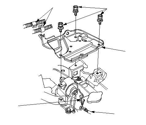 8 x 1.25 mm 8 x 1.25 mm22 N·m (2.2 kgf·m, 16 lbf·ft)C6 x 1.0 mm 9.8 N·m (1.0 kgf·m, 7.2 lbf·ft)AB |
| 32. | Install the air cleaner housing. |
| 33. | Install the battery. Connect the positive (+) cable first, then the negative (-) cable to the battery. |
| 34. | Refill the transmission fluid. |
| 35. | Test-drive the vehicle. |
| 36. | Check the clutch operation. |
| 37. | Check the transmission for noise and smooth operation. |
| 38. | Check the front wheel alignment. |
| 39. | Enter the anti-theft code for the radio, then enter the customer's radio station presets. |