Rear Stabilizer Link Removal/Installation (4D)
Rear Stabilizer Link Removal/Installation
| 1. | Raise the rear of the vehicle, and support it with safety stands in the proper locations. Remove the rear wheels. |
| 2. | Remove the self-locking nut (A) and flange nut (B) while holding the respective joint pin (C) with a hex wrench (D), and remove the stabilizer link (E).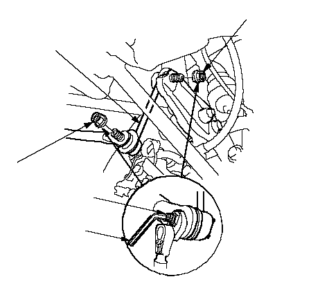 B B10 x 1.25 mmA 10 x 1.25 mmCDE |
| 3. | Install the stabilizer link (A) on the stabilizer bar (B) and stabilizer link bracket (C) with the joint pins set at the center of their range of the movement. NOTE: The left stabilizer link has a white paint mark (D), while the right stabilizer link has a yellow paint mark. 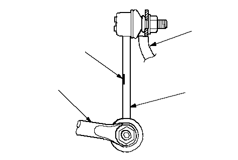 CABD CABD |
| 4. | Install the new self-locking nut and flange nut, and lightly tighten them. NOTE: Use a new self-locking nut on reassembly. |
| 5. | Place a jack under the knuckle, and raise the suspension to load it with the vehicle's weight. |
| 6. | Tighten the self-locking nut (A) and flange nut (B) to the specified torque values while holding the respective joint pins (C) with a hex wrench (D).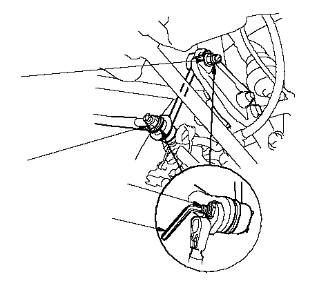 B B10 x 1.25 mm 39 N·m (4.0 kgf·m, 29 lbf·ft)A 10 x 1.25 mm 38 N·m (3.9 kgf·m, 28 lbf·ft)DC |
| 7. | After 5 minutes of driving, re-tighten the self-locking nut again to the specified torque. |