Rear Knuckle/Hub Replacement (4D)
Rear Knuckle/Hub Replacement
Exploded View
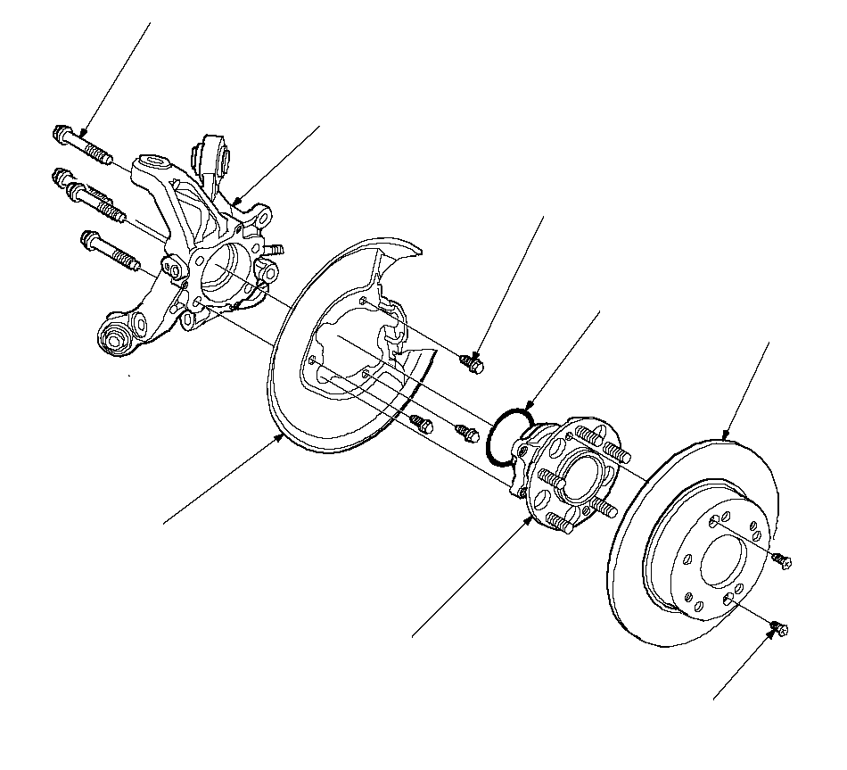 KNUCKLE
Check for deformation
and damage.6 x 1.0 mm
9.8 N·m
(1.0 kgf·m, 7.2 lbf·ft)O-RING
Replace.SPLASH GUARD
Check for corrosion,
deformation,
and damage.
Replace if rusted.HUB BEARING UNIT
Check for faulty movement
and wear.FLAT SCREW
6 x 1.0 mm
9.8 N·m
(1.0 kgf·m,7.2 lbf·ft)BRAKE DISK10 x 1.25 mm
64 N·m
(6.5 kgf·m, 47 lbf·ft)
Special Tools Required
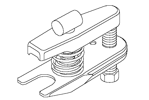
Ball joint remover, 28 mm ( 07MAC-SL00200)
Hub Replacement
| 1. | Raise the rear of the vehicle, and support it with safety stands in the proper locations. |
| 2. | Remove the wheel nuts, and rear wheel.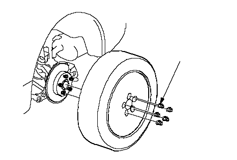 108 N·m 108 N·m (11.0 kgf·m, 80 lbf·ft) |
| 3. | Remove the brake hose mounting bracket (A).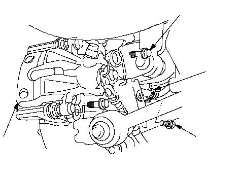 8 x 1.25 mm 8 x 1.25 mm22 N·m (2.2 kgf·m, 16 lbf·ft)B 10 x 1.25 mm 74 N·m (7.5 kgf·m, 54 lbf·ft)AC |
| 4. | Remove the brake caliper bracket mounting bolts (B), and remove the caliper assembly (C) from the knuckle. To prevent damage to the caliper assembly or brake hose, use a short piece of wire to hang the caliper assembly from the undercarriage. Do not twist the brake hose with force. |
| 5. | Remove the two washers (A).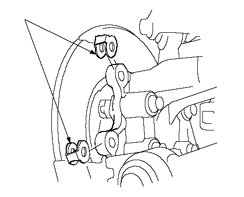 A A |
| 6. | Remove the 6 mm brake disc retaining screws (A).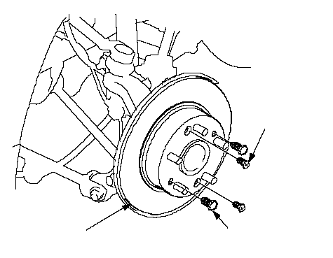 CA CA6 x 1.0 mm 9.8 N·m (1.0 kgf·m, 7.2 lbf·ft)B 8 x 1.25 mm |
| 7. | Screw two 8 x 1.25 mm bolts (B) into the disc to push it away from the hub. Turn each bolt two turns at a time to prevent cocking the disc excessively. |
| 8. | Remove the brake disc (C). |
| 9. | Remove the hub bearing unit (A) and O-ring (B).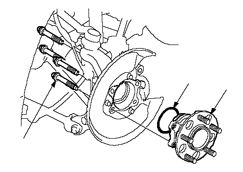 10 x 1.25 mm 10 x 1.25 mm64 N·m (6.5 kgf·m, 47 lbf·ft)BA |
| 10. | Install the hub bearing unit in the reverse order of removal, and note these items:
|
Knuckle Replacement
| 1. | Remove the hub bearing unit. |
| 2. | Remove the splash guard (A).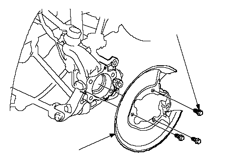 A6 x 1.0 mm A6 x 1.0 mm9.8 N·m (1.0 kgf·m, 7.2 lbf·ft) |
| 3. | Remove the clip (A) from the upper arm ball joint, and loosen the nut (B). NOTE: During installation, install the new clip after tightening the nut as shown. 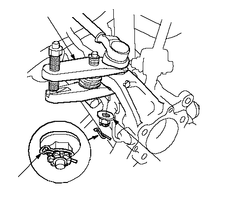 B B12 x 1.25 mm 54-64 N·m (5.5-6.5 kgf·m, 40-47 lbf·ft)A07MAC-SL00200 |
| 4. | Disconnect the upper arm ball joint from the knuckle using the special tool. |
| 5. | Remove the flange nut (A) while holding the joint pin (B) with a hex wrench (C) stabilizer link (D) from the stabilizer link bracket (E).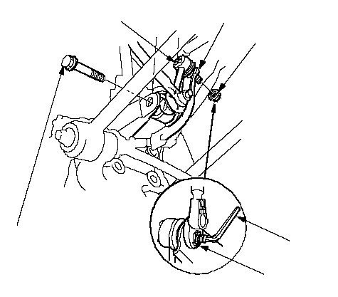 A A10 x 1.25 mm 39 N·m (4.0 kgf·m, 29 lbf·ft)F 12 x 1.25 mm 108 N·m (11.0 kgf·m, 79.6 lbf·ft)BCDE |
| 6. | Remove the damper lower mounting bolt (F) and disconnect the damper from the knuckle. |
| 7. | Remove the wheel sensor (A) from the knuckle. Do not disconnect the wheel sensor connector.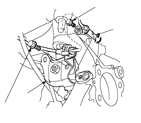 6 x 1.0 mm 6 x 1.0 mm9.8 N·m (1.0 kgf·m, 7.2 lbf·ft)10 x 1.25 mm 44 N·m (4.5 kgf·m, 33 lbf·ft)BA |
| 8. | Remove the stabilizer link bracket (B) from the knuckle. |
| 9. | Remove the leading arm mounting bolt (A) from the knuckle.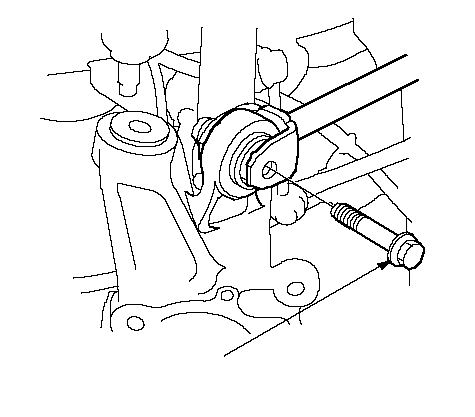 A A12 x 1.25 mm 59 N·m (6.0 kgf·m, 43 lbf·ft) |
| 10. | Remove the control arm mounting nut (A) and washer (B).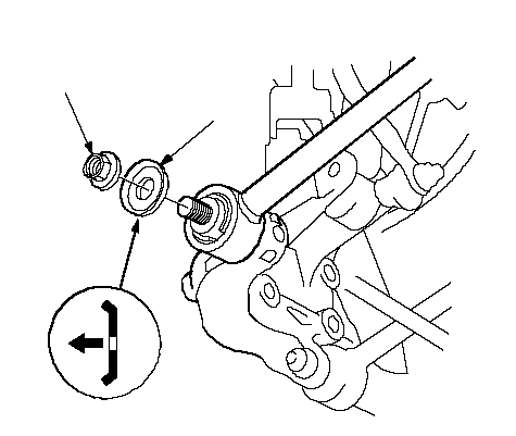 A A12 x 1.25 mm 69 N·m (7.0 kgf·m, 51 lbf·ft)B |
| 11. | Remove the trailing arm mounting bolt (A) from the knuckle.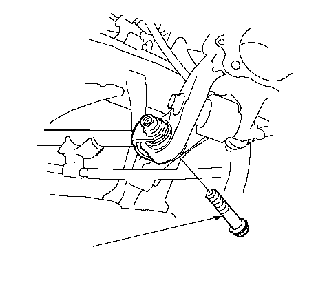 A A12 x 1.25 mm 59 N·m (6.0 kgf·m, 43 lbf·ft) |
| 12. | Remove the lower arm mounting bolt (A), and remove the knuckle (B).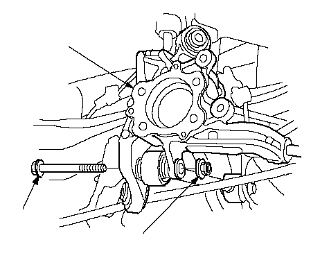 AB12 x 1.25 mm AB12 x 1.25 mm108 N·m (11.0 kgf·m, 79.6 lbf·ft) |
| 13. | Install the knuckle in the reverse order of removal, and note these items:
|