DTC Troubleshooting: 27 (VSA)
DTC Troubleshooting: 27
| DTC 27: | Steering Angle Sensor |
| 1. | Clear the DTC. |
| 2. | Turn the ignition switch OFF, then turn it ON (II) again. |
| 3. | Test-drive the vehicle around a number of corners. |
| 4. | Verify the DTC. Is DTC 64 indicated? YES - Do the appropriate troubleshooting for the DTC.n NO - Go to 5. |
| 5. | Turn the ignition switch OFF. |
| 6. | Disconnect the VSA control unit 47P connector, steering angle sensor 5P connector and yaw rate/lateral acceleration sensor 5P connector. |
| 7. | Turn the ignition switch ON (II). |
| 8. | Measure the voltage between body ground and the VSA control unit 47P connector terminal No. 33, No. 35 individually.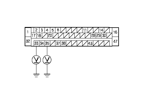 Wire side of female terminalsVSA CONTROL UNIT 47P CONNECTORSVCC (ORN)SGND Wire side of female terminalsVSA CONTROL UNIT 47P CONNECTORSVCC (ORN)SGND(GRY/WHT) Is there 1 V or more? YES - Repair short to power in the wire between the VSA control unit and the steering angle sensor.n NO - Go to 9. |
| 9. | Measure the voltage between body ground and the VSA control unit 47P connector terminal No. 28, No. 29, No. 43 individually.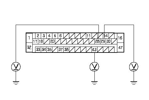 Wire side of female terminalsVSA CONTROL UNIT 47P CONNECTORSTR-B Wire side of female terminalsVSA CONTROL UNIT 47P CONNECTORSTR-B(BLU/YEL)STR-D (BLU/ORN)STR-A (BLU) Is there 1 V or more? YES - Repair short to power in the wire between the VSA control unit and the steering angle sensor.n NO - Go to 10. |
| 10. | Turn the ignition switch OFF. |
| 11. | Check for continuity between body ground and the VSA contol unit 47P connector terminal No. 33, No. 35 individually.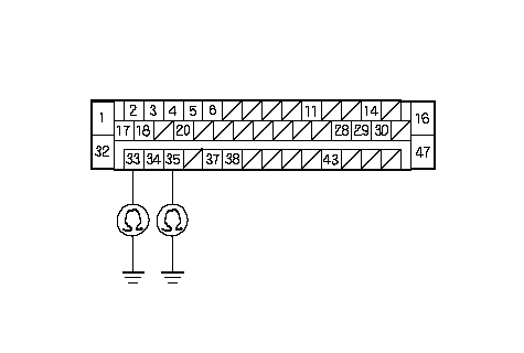 Wire side of female terminalsVSA CONTROL UNIT 47P CONNECTORSVCC (ORN)SGND Wire side of female terminalsVSA CONTROL UNIT 47P CONNECTORSVCC (ORN)SGND(GRY/WHT) Is there continuity? YES - Repair short to body ground in the wire between the VSA control unit and the steering angle sensor.n NO - Go to 12. |
| 12. | Check for continuity between body ground and the VSA contol unit 47P connector terminal No. 28, No. 29, No.43 individually.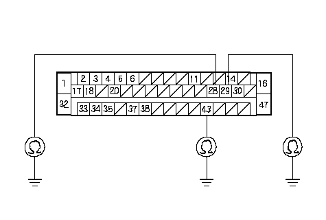 Wire side of female terminalsVSA CONTROL UNIT 47P CONNECTORSTR-B Wire side of female terminalsVSA CONTROL UNIT 47P CONNECTORSTR-B(BLU/YEL)STR-D (BLU/ORN)STR-A (BLU) Is there continuity? YES - Repair short to body ground in the wire between the VSA control unit and the steering angle sensor.n NO - Go to 13. |
| 13. | Check for continuity between the VSA contol unit 47P connector terminal No. 33, No. 35 and steering angle sensor 5P connector terminal No. 1, No. 5 individually.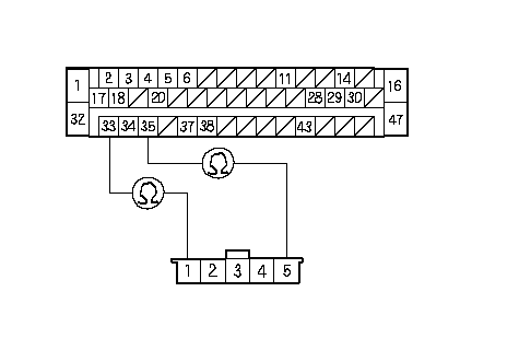 Wire side of female terminalsVSA CONTROL UNIT 47P CONNECTORSGND Wire side of female terminalsVSA CONTROL UNIT 47P CONNECTORSGND(GRY/WHT)STEERING ANGLE SENSOR 5P CONNECTORSVCC (ORN) Is there continuity? YES - Go to 14. NO - Repair open in the wire between the VSA control unit and the steering angle sensor.n |
| 14. | Check for continuity between the VSA contol unit 47P connector terminal No. 28, No. 29, No. 43 and steering angle sensor 5P connector terminal No. 2, No. 3, No. 4 individually.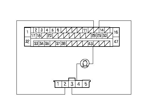 Wire side of female terminalsVSA CONTROL UNIT 47P CONNECTORSTEERING ANGLE Wire side of female terminalsVSA CONTROL UNIT 47P CONNECTORSTEERING ANGLESENSOR 5P CONNECTORSTR-A (BLU)STR-D (BLU/ORN)STR-B (BLU/YEL) Is there continuity? YES - Go to 15. NO - Repair open in the wire between the VSA control unit and the steering angle sensor.n |
| 15. | Substitute a known-good steering angle sensor. |
| 16. | Reconnect all of disconnected connectors. |
| 17. | Clear the DTC. |
| 18. | Test-drive the vehicle around a number of corners. |
| 19. | Verify the DTC. Is DTC 27 indicated? YES - Replace the VSA modulator-control unit.n |