DTC Troubleshooting: 11, 13, 15, 17 (VSA)
DTC Troubleshooting: 11, 13, 15, 17
| DTC 11, 13, 15, 17: | Wheel Sensor (Open/Short to Body Ground/Short to Power) |
| 1. | Disconnect the VSA control unit 47P connector. |
| 2. | Start the engine. |
| 3. | Measure the voltage between body ground and the appropriate wheel sensor +B and GND terminals of the VSA control unit 47P connector individually (see table).
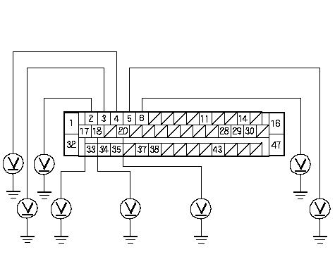 Wire side of female terminalsVSA CONTROL UNIT 47P CONNECTORFR +B Wire side of female terminalsVSA CONTROL UNIT 47P CONNECTORFR +B(GRN/BLK)FR -GND (PNK)FL -GND (BRN/WHT)FL +B (BLU/WHT)RL -GND (RED)RL +B (YEL/RED)RR +B (GRN/YEL)RR -GND (BLU/YEL) Is there 1 V or more? YES - Repair short to power in the wire between the VSA modulator-control unit and the appropriate wheel sensor.n NO - Go to 4. | |||||||||||||||||
| 4. | Turn the ignition switch OFF. |
| 5. | Check for continuity between body ground and the appropriate wheel sensor +B and GND terminals of the VSA control unit 47P connector individually (see table).
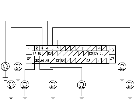 Wire side of female terminalsVSA CONTROL UNIT 47P CONNECTORFR +B Wire side of female terminalsVSA CONTROL UNIT 47P CONNECTORFR +B(GRN/BLK)FR -GND (PNK)FL -GND (BRN/WHT)FL +B (BLU/WHT)RL -GND (RED)RL +B (YEL/RED)RR +B (GRN/YEL)RR -GND (BLU/YEL) Is there continuity? YES - Go to 6. NO - Go to 8. | |||||||||||||||||
| 6. | Disconnect the appropriate wheel sensor 2P connector. |
| 7. | Check for continuity between body ground and the appropriate wheel sensor +B and GND terminals of the VSA control unit 47P connector individually (see table).
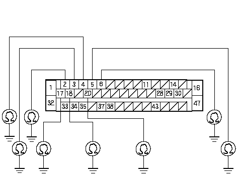 Wire side of female terminalsVSA CONTROL UNIT 47P CONNECTORFR +B Wire side of female terminalsVSA CONTROL UNIT 47P CONNECTORFR +B(GRN/BLK)FR -GND (PNK)FL -GND (BRN/WHT)FL +B (BLU/WHT)RL -GND (RED)RL +B (YEL/RED)RR +B (GRN/YEL)RR -GND (BLU/YEL) Is there continuity? YES - Repair short to body ground in the wire between the VSA modulator-control unit and the wheel sensor.n | |||||||||||||||||
| 8. | Mesure the resistance between the appropriate wheel sensor +B and GND terminals of the VSA control unit 47P connector (see table), then measure the resistance between the same terminals after changing the positive tester probe and negative tester probe.
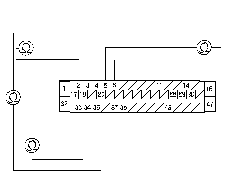 Wire side of female terminalsVSA CONTROL UNIT 47P CONNECTORFR +B (GRN/BLU)FR -GND Wire side of female terminalsVSA CONTROL UNIT 47P CONNECTORFR +B (GRN/BLU)FR -GND(PNK)FL -GND (BRN/WHT)FL +B (BLU/WHT)RL -GND (RED)RL+ B (YEL/RED)RR +B (GRN/YEL)RR -GND (BLU/YEL) Is the resistance infinity (open circuit) in both directions? YES - Go to 9. NO - Go to 11. | |||||||||||||||||
| 9. | Disconnect the appropriate wheel sensor 2P connector. |
| 10. | Measure the resistance between the appropriate wheel sensor 2P connector terminals, then remeasure the resistance between the same terminals after changing the positive tester probe and negative tester probe.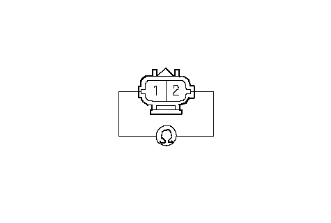 WHEEL SENSOR 2P CONNECTORWire side of female terminals WHEEL SENSOR 2P CONNECTORWire side of female terminalsIs the resistance infinity (open circuit) in both directions? YES - Replace the wheel sensor.n NO - Repair short to body ground in the wire between the VSA modulator-control unit and the wheel sensor.n |
| 11. | Check for continuity between the appropriate wheel sensor +B and GND terminals of the VSA control unit 47P connector (see table), then recheck for continuity between the same terminals after changing the positive tester probe and negative tester probe.
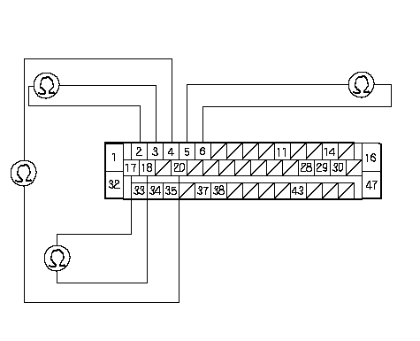 Wire side of female terminalsVSA CONTROL UNIT 47P CONNECTORFR +B (GRN/BLU)FR -GND Wire side of female terminalsVSA CONTROL UNIT 47P CONNECTORFR +B (GRN/BLU)FR -GND(PNK)FL -GND (BRN/WHT)FL +B (BLU/WHT)RL -GND (RED)RL+ B (YEL/RED)RR +B (GRN/YEL)RR -GND (BLU/YEL) Is there continuity in both directions? YES - Go to 12. NO - Check for a loose VSA control unit 47P connector. If necessary, substitute a known-good VSA modulator-control unit, and recheck.n | |||||||||||||||||
| 12. | Disconnect the appropriate wheel sensor 2P connector. |
| 13. | Check for continuity between the appropriate wheel sensor 2P connector terminals, then recheck for continuity between the same terminals after changing the positive tester probe and negative tester probe.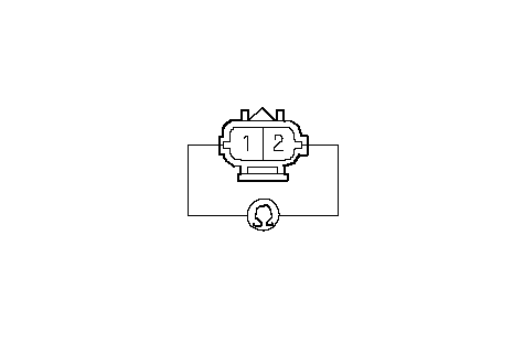 WHEEL SENSOR 2P CONNECTORWire side of female terminals WHEEL SENSOR 2P CONNECTORWire side of female terminalsIs there continuity in both directions? YES - Replace the wheel sensor.n NO - Repair short to body ground in the wire between the VSA modulator-control unit and the wheel sensor.n |