A/T System Description (A/T)
A/T System Description
General Operation
The automatic transmission is a combination of a 3-element torque converter and triple-shaft electronically controlled unit which provides 5 speeds forward and 1 reverse. The entire unit is positioned in line with the engine.Torque Converter, Gears, and Clutches
The torque converter consists of a pump, turbine, and stator assembly in a single unit. The converter housing (pump) is connected to the engine crankshaft and turns as the engine turns. Around the outside of the torque converter is a ring gear which meshes with the starter pinion when the engine is being started. The entire torque converter assembly serves as a flywheel while transmitting power to the transmission mainshaft, the transmission has three parallel shafts; the mainshaft, the countershaft, the secondary shaft. The mainshaft is in line with the engine crankshaft, and includes the 4th and 5th clutches, and gears for 5th, 4th, reverse, and idler. The mainshaft reverse gear is integral with the mainshaft 4th gear. The countershaft includes the gears for 1st, 2nd, 3rd, 4th, 5th, reverse, park, and the final drive. The final drive gear is integral with the countershaft. The countershaft 4th gear and the countershaft reverse gear can be locked to the countershaft providing 4th or reverse gear, depending on which way the selector is moved. The secondary shaft includes the 1st, 2nd, and 3rd clutches, and gears for 1st, 2nd, 3rd, and idler. The idler shaft is located between the mainshaft and secondary shaft, and the idler gear transmits power between the mainshaft and the secondary shaft. The gears on the mainshaft and the secondary shaft are in constant mesh with those on the countershaft. When certain combinations of gears in the transmission are engaged by the clutches, power is transmitted through the mainshaft then to the secondary shaft, and/or to the countershaft to provide drive.Electronic Control
The electronic control system consists of the powertrain control module (PCM), sensors, and solenoid valves. Shifting and lock-up are electronically controlled for comfortable driving under all conditions. The PCM is located below the dashboard, under the front lower panel behind the center console.Hydraulic Control
The valve bodies include the main valve body, the regulator valve body, and the servo body. They are bolted to the torque converter housing. The main valve body contains the manual valve, the shift valves A, B, C, and E, the relief valve, the lock-up control valve, the cooler check valve, the servo control valve, and the ATF pump gears. The regulator valve body contains the regulator valve, the torque converter check valve, lock-up shift valve, and the 1st and 3rd accumulators. The servo body contains the servo valve, shift valve D, accumulators for 2nd, 4th, and 5th, and shift solenoid valves for A, B, C, D, and E. Fluid from the regulator passes through the manual valve to the various control valves. The 1st, 3rd, 5th clutches receive fluid from their respective feed pipes, and the 2nd and the 4th clutches receive fluid from the internal hydraulic circuit.Shift Control Mechanism
The PCM controls shifts via the shift solenoid valves A, B, C, D, and E, and the A/T clutch pressure control solenoid valves A, B, and C, while receiving input signals from various sensors and switches located throughout the vehicle. The shift solenoid valves shift the positions of the shift valves to switch the port leading hydraulic pressure to the clutch. The A/T clutch pressure control solenoid valves A, B, and C regulate their respective pressure, and pressurize the clutches to engage it and its corresponding gear. The pressures of the A/T clutch pressure control solenoid valves also apply to the shift valves to switch the port.Lock-up Mechanism
The lock-up mechanism operates in [D] position (2nd, 3rd, 4th and 5th), in [D3] position (2nd and 3rd), and in [M] (manual mode) position (3rd, 4th, and 5th). The pressurized fluid is drained from the back of the torque converter through a fluid passage, causing the torque converter clutch piston to be held against the torque converter cover. As this takes place, the mainshaft rotates at the same speed as the engine crankshaft. Together with the hydraulic control, the PCM optimizes the timing and volume of the lock-up mechanism. When the shift solenoid valve E is turned on by the PCM, shift solenoid valve E pressure switches the lock-up shift valve on and off. The A/T clutch pressure control solenoid valve A and the lock-up control valve control the volume of the lock-up conditions.Gear Selection
The shift lever has five positions: [P] PARK, [R] REVERSE, [N] NEUTRAL, [D] DRIVE 1st through 5th gear range with automatic shift and manual shift in [M] (manual mode) position, and [D3] DRIVE 1st through 3rd gear range with automatic shift.| Position | Description | |
|---|---|---|
| [P] PARK | Front wheels locked; park pawl engaged with park gear on countershaft. All clutches are released. | |
| [R] REVERSE | Reverse; reverse selector engaged with countershaft reverse gear and 4th clutch engaged. | |
| [N] NEUTRAL | All clutches are released. | |
| [D] DRIVE (1st through 5th) | Automatic shift | General driving; starts off in 1st, shifts automatically to 2nd, 3rd, 4th, then 5th, depending on vehicle speed and throttle position. Downshifts through 4th, 3rd, 2nd, and 1st on deceleration to stop. The lock-up mechanism operates in 2nd, 3rd, 4th and 5th gears. |
| [M] position Manual mode | Manual gear shift driving; vehicle can starts off in 1st and 2nd gears, and does not upshift automatically. The lock-up mechanism operates in 3rd, 4th and 5th gears. | |
| [D3] DRIVE (1st through 3rd) | For rapid acceleration at highway speeds and general driving, up-hill and down-hill driving; starts off in 1st, shifts automatically to 2nd, then 3rd, depending on vehicle speed and throttle position. Downshifts through 2nd to 1st on deceleration to stop. The lock-up mechanism operates in 2nd and 3rd gears. | |
Starting is possible only in [P] and [N] positions because of a slide-type neutral-safety switch.
Automatic Transaxle (A/T) Gear Position Indicator
The A/T gear position indicator in the instrument panel shows which position has been selected without having to look down at the shift lever. With the shift lever in the [M] (manual mode) position, the shift indicator between the speedometer and tachometer in the instrument panel will display the gear selected.Clutches and Gears
The 5-speed automatic transmission uses hydraulically-actuated clutches to engage or disengage the transmission gears. When hydraulic pressure is introduced into the clutch drum, the clutch piston moves. This presses the friction discs and steel plates together, locking them so they don't slip. Power is then transmitted through the engaged clutch pack to its hub-mounted gear. Likewise, when the hydraulic pressure is bled from the clutch pack, the piston releases the friction discs and steel plates, and they are free to slide past each other. This allows the gear to spin independently on its shaft, transmitting no power.
1st Clutch
The 1st clutch engages/disengages 1st gear, and is located at the middle of the secondary shaft. The 1st clutch is joined back-to-back to the 3rd clutch. The 1st clutch is supplied hydraulic pressure by its ATF feed pipe within the secondary shaft.2nd Clutch
The 2nd clutch engages/disengages 2nd gear, and is located at the end of the secondary shaft, opposite the end cover. The 2nd clutch is supplied hydraulic pressure by a circuit connected to the internal hydraulic circuit.3rd Clutch
The 3rd clutch engages/disengages 3rd gear, and is located at the middle of the secondary shaft. The 3rd clutch is joined back-to-back to the 1st clutch. The 3rd clutch is supplied hydraulic pressure by its ATF feed pipe within the secondary shaft.4th Clutch
The 4th clutch engasges/disengages 4th gear, as well as reverse gear, and is located at the middle of the mainshaft. The 4th clutch is joined back-to-back to the 5th clutch. The 4th clutch is supplied hydraulic pressure by its ATF feed pipe within the mainshaft.5th Clutch
The 5th clutch engages/disengages 5th gear, and is located at the middle of the mainshaft. The 5th clutch is joined back-to-back to the 4th clutch. The 5th clutch is supplied hydraulic pressure by its ATF feed pipe within the mainshaft.Gear operation
Gears on the mainshaft:- 4th gear engages/disengages with the mainshaft by the 4th clutch.
- 5th gear engages/disengages with the mainshaft by the 5th clutch.
- Reverse gear engages/disengages with the mainshaft by the 4th clutch.
- Idler gear is splined with the mainshaft, and rotates with the mainshaft.
Gears on the countershaft:
- Final drive gear is integral with the countershaft.
- 1st, 2nd, 3rd, 5th, and park gears are splined with the countershaft, and rotate with the countershaft.
- 4th gear and reverse gear rotate freely from the countershaft. The reverse selector engages 4th gear and reverse gear with the reverse selector hub. The reverse selector hub is splined to the countershaft so that the 4th gear and reverse gear engage with the countershaft.
Gears on the secondary shaft:
- 1st gear engages/disengages with the secondary shaft by the 1st clutch.
- 2nd gear engages/disengages with the secondary shaft by the 2nd clutch.
- 3rd gear engages/disengages with the secondary shaft by the 3rd clutch.
- Idler gear is splined with the secondary shaft, and rotates with the secondary shaft.
The idler gear on the idler shaft transmits power between the mainshaft and the secondary shaft.
The reverse idler gear transmits power from the mainshaft reverse gear to the countershaft reverse gear, and changes rotation direction of the countershaft to reverse.
Transmission Cutaway View
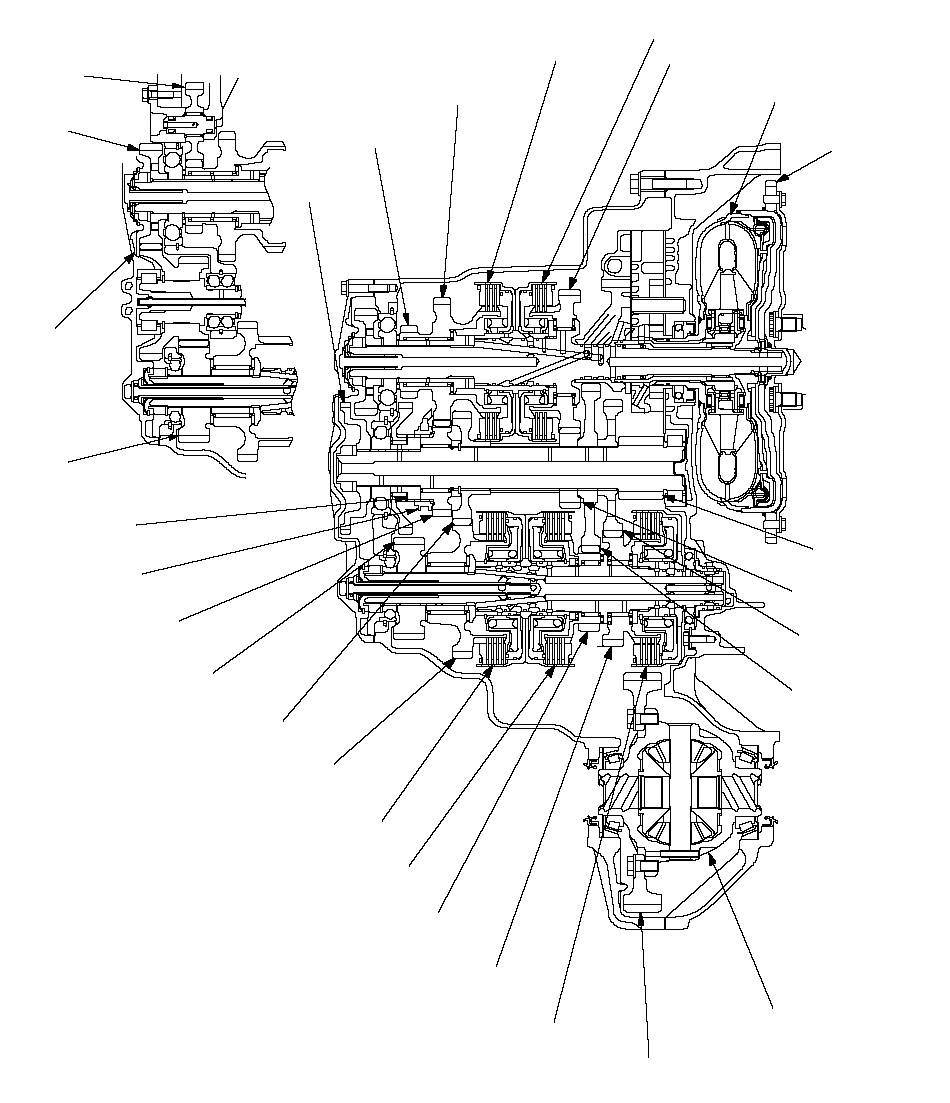 SECONDARY
 SHAFT IDLER
GEARMAINSHAFT 5TH GEARMAINSHAFT
REVERSE GEARMAINSHAFT
4TH GEAR4TH CLUTCH3RD CLUTCHRING GEARTORQUE CONVERTERCOUNTERSHAFT
3RD GEARCOUNTERSHAFT
1ST GEARDIFFERENTIAL
ASSEMBLYFINAL DRIVEN GEARSECONDARY SHAFT
1ST GEAR1ST CLUTCHSECONDARY SHAFT
2ND GEARCOUNTERSHAFT
4TH GEARREVERSE SELECTORPARK GEARREVERSE SELECTOR
HUBCOUNTERSHAFT
2ND GEARCOUNTERSHAFT
REVERSE GEARCOUNTERSHAFT
5TH GEAR5TH CLUTCHSECONDARY SHAFT
3RD GEARIDLER SHAFT
IDLER GEARREVERSE
IDLER GEARMAINSHAFT
IDLER GEARIdler Gears Section Cutway View2ND CLUTCHFINAL DRIVE
GEAR
Power Flow (cont'd)
[P] Position
Hydraulic pressure is not applied to the clutches. Power is not transmitted to the countershaft. The countershaft is locked by the park pawl, interlocking the park gear.[N] Position
Engine power transmitted from the torque converter drives the mainshaft idler gear, the idler shaft idler gear, and the secondary idler gear, but hydraulic pressure is not applied to the clutches. Power is not transmitted to the countershaft.
In this position, the position of the reverse selector differs according to whether the shift lever shifted from [D] or [R] position:
- When shifted from [D] position, the reverse selector engages with the countershaft 4th gear and the reverse selector hub, and the 4th gear engages with the countershaft.
- When shifted from [R] position, the reverse selector engages with the countershaft reverse gear and the reverse selector hub, and the reverse gear engages with the countershaft.
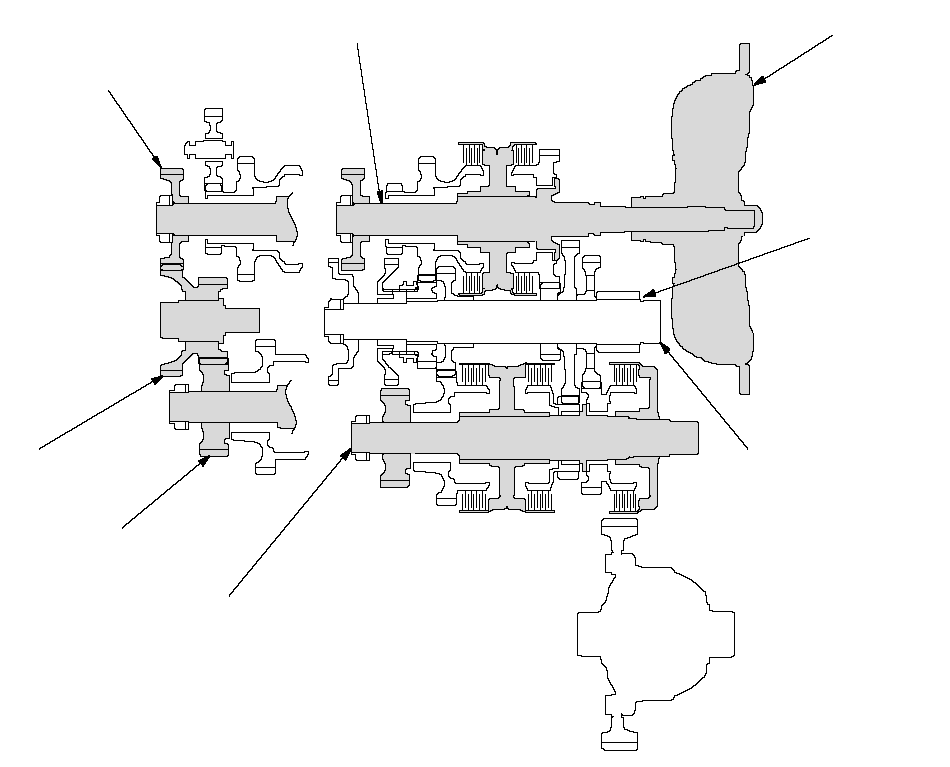 TORQUE
 CONVERTERMAINSHAFTCOUNTERSHAFTFINAL DRIVE
GEARMAINSHAFT
IDLER GEARSECONDARY SHAFTSECONDARY SHAFT
IDLER GEARIDLER SHAFT
IDLER GEAR
1st Gear
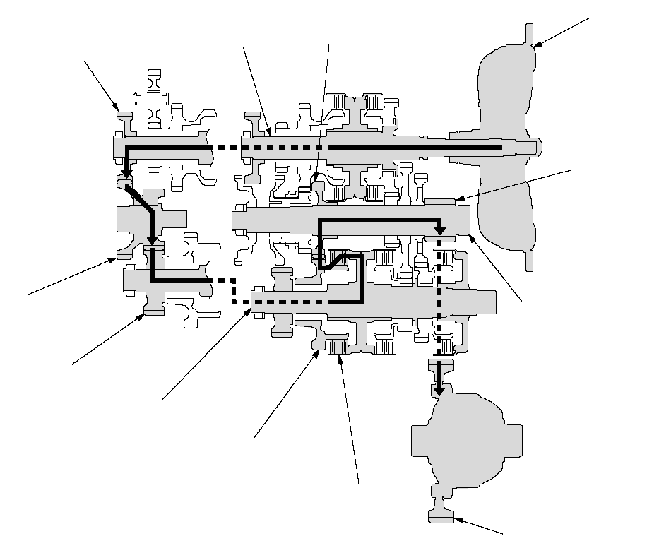
- Hydraulic pressure is applied to the 1st clutch, then the 1st clutch engages the secondary shaft 1st gear with the secondary shaft.
- The mainshaft idler gear drives the secondary shaft via the idler shaft idler gear and the secondary shaft idler gear.
- The secondary shaft 1st gear drives the countershaft 1st gear and the countershaft.
- Power is transmitted to the final drive gear, which in turn drives the final driven gear.
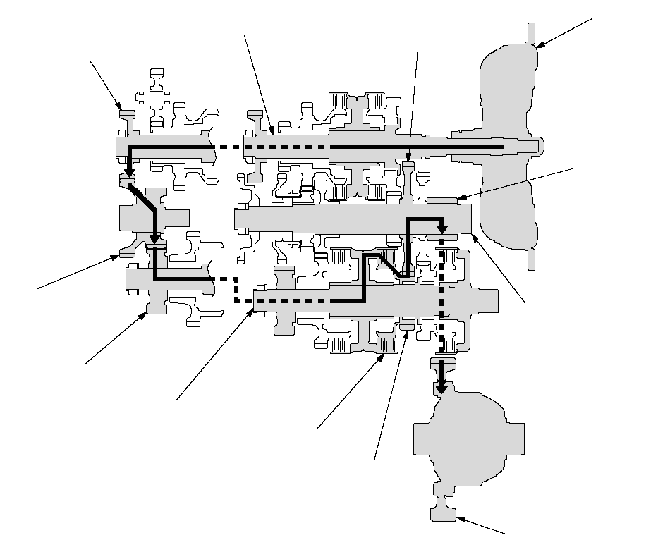 TORQUE
 CONVERTERMAINSHAFTCOUNTERSHAFTCOUNTERSHAFT
1ST GEARFINAL DRIVE
GEARMAINSHAFT
IDLER GEAR1ST CLUTCHSECONDARY SHAFT
1ST GEARSECONDARY SHAFTSECONDARY SHAFT
IDLER GEARIDLER SHAFT
IDLER GEARFINAL DRIVEN GEAR
Power Flow (cont'd)
2nd Gear
- Hydraulic pressure is applied to the 2nd clutch, then the 2nd clutch engages the secondary shaft 2nd gear with the secondary shaft.
- The mainshaft idler gear drives the secondary shaft via the idler shaft idler gear and the secondary shaft idler gear.
- The secondary shaft 2nd gear drives the countershaft 2nd gear and the countershaft.
- Power is transmitted to the final drive gear, which in turn drives the final driven gear.
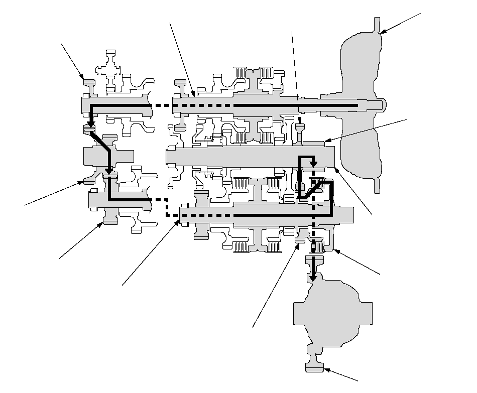 TORQUE
 CONVERTERMAINSHAFTCOUNTERSHAFTCOUNTERSHAFT
2ND GEARFINAL DRIVE
GEARMAINSHAFT
IDLER GEAR2ND CLUTCHSECONDARY SHAFT
2ND GEARSECONDARY SHAFTSECONDARY SHAFT
IDLER GEARIDLER SHAFT
IDLER GEARFINAL DRIVEN GEAR
3rd gear
- Hydraulic pressure is applied to the 3rd clutch, then the 3rd clutch engages the secondary shaft 3rd gear with the secondary shaft.
- The mainshaft idler gear drives the secondary shaft via the idler shaft idler gear and secondary shaft idler gear.
- The secondary shaft 3rd gear drives the countershaft 3rd gear and the countershaft.
- Power is transmitted to the final drive gear, which in turn drives the final driven gear.
 TORQUE
 CONVERTERMAINSHAFTCOUNTERSHAFTCOUNTERSHAFT
3RD GEARFINAL DRIVE
GEARMAINSHAFT
IDLER GEAR3RD CLUTCHSECONDARY SHAFT
3RD GEARSECONDARY SHAFTSECONDARY SHAFT
IDLER GEARIDLER SHAFT
IDLER GEARFINAL DRIVEN GEAR
Power Flow (cont'd)
4th gear
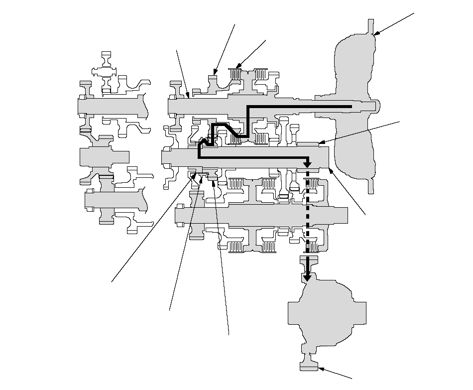
- Hydraulic pressure is applied to the servo valve to engage the reverse selector with the countershaft 4th gear and reverse selector hub while the shift lever is in the [D], [D3], [M] position (forward range).
- Hydraulic pressure is also applied to the 4th clutch, then the 4th clutch engages the mainshaft 4th gear with the mainshaft.
- The mainshaft 4th gear drives the countershaft 4th gear and the countershaft.
- Power is transmitted to the final drive gear, which in turn drives the final driven gear.
 TORQUE
 CONVERTERMAINSHAFTCOUNTERSHAFTMAINSHAFT
4TH GEARFINAL DRIVE
GEAR4TH CLUTCHREVERSE SELECTOR HUBFINAL DRIVEN GEARREVERSE SELECTORCOUNTERSHAFT
4TH GEAR
5th gear
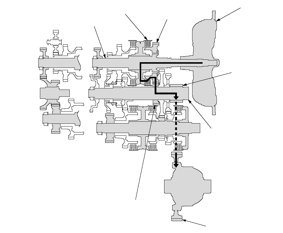
- Hydraulic pressure is applied to the 5th clutch, then the 5th clutch engages the mainshaft 5th gear with the mainshaft.
- The mainshaft 5th gear drives the countershaft 5th gear and the countershaft.
- Power is transmitted to the final drive gear, which in turn drives the final driven gear.
 TORQUE
 CONVERTERMAINSHAFTCOUNTERSHAFTMAINSHAFT
5TH GEARFINAL DRIVE
GEAR5TH CLUTCHFINAL DRIVEN GEARCOUNTERSHAFT
5TH GEAR
Power Flow (cont'd)
[R] Position
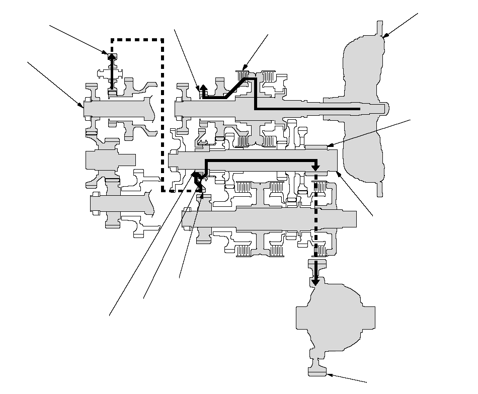
- Hydraulic pressure is applied to the servo valve to engage the reverse selector with the countershaft reverse gear and reverse selector hub while the shift lever is in the [R] position.
- Hydraulic pressure is also applied to the 4th clutch, then the 4th clutch engages the mainshaft reverse gear with the mainshaft.
- The mainshaft reverse gear drives the countershaft reverse gear via the reverse idler gear.
- The rotation direction of the countershaft reverse gear is changed by the reverse idler gear.
- The countershaft reverse gear drives the countershaft via the reverse selector, which drives the reverse selector hub.
- Power is transmitted to the final drive gear, which in turn drives the final driven gear.
 TORQUE
 CONVERTERCOUNTERSHAFTREVERSE
IDLER GEARFINAL DRIVE
GEARCOUNTERSHAFT
REVERSE GEARREVERSE SELECTORMAINSHAFT4TH CLUTCHREVERSE SELECTOR HUBFINAL DRIVEN GEARMAINSHAFT
REVERSE GEAR
Electronic Control System
Functional Diagram
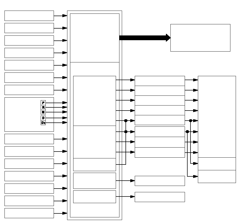
The electronic control system consists of the powertrain control module (PCM), sensors, and solenoid valves.
Shifting and lock-up are electronically controlled for comfortable driving under all conditions.
The PCM recieves input signals from the sensors, switches, and other control units, perform processing data, and outputs signals for the engine control system and A/T control system. The A/T control system includes shift control, grade logic control, clutch pressure control, and lock-up control is stored in the PCM.
The PCM switches the shift solenoid valves and the A/T clutch pressure control solenoid valves to control shifting transmission gears and lock-up torque converter clutch.
 PCMEngine RPM SignalThrottle Position
 Sensor SignalEngine Coolant
Temperature Sensor SignalBarometric Pressure
Sensor SignalManifold Absolute
Pressure Sensor SignalTransmission
Range
Switch
SignalMainshaft Speed
Sensor SignalCountershaft Speed
Sensor SignalBrake Pedal Position
Switch SignalPGM-FI Control
SystemA/T Control SystemShift ControlGrade Logic Control·Ascending controlDescending control·Clutch Pressure
ControlLock-up ControlGauge Assembly
A/T Gear Position Indicator
Manual Mode
Position Shift IndicatorShift Solenoid Valve AShift Solenoid Valve BA/T Clutch Pressure
Control Solenoid Valve AA/T Clutch Pressure
Control Solenoid Valve BVehicle Speed Signal
Data Link ConnectorShift Lock SolenoidAutomatic
5-speed and
ReverseLock-up
ConditionsLock-up
ON/OFFService Check SignalATF Temperature
Sensor SignalTransmission Gear
Selection Switch Signal2nd Clutch Pressure
Switch Signal3rd Clutch Pressure
Switch SignalSelf-diagnosis/
Fail-safe Function
Communication and
Output FunctionShift Lock Control
Reverse Lock ControlShift Solenoid Valve CA/T Clutch Pressure
Control Solenoid Valve CShift Solenoid Valve DShift Solenoid Valve EMultiplexCruise Control Unit
Downshift Request Signal
Electronic Control System (cont'd)
Electronic Controls Location
Cabin:
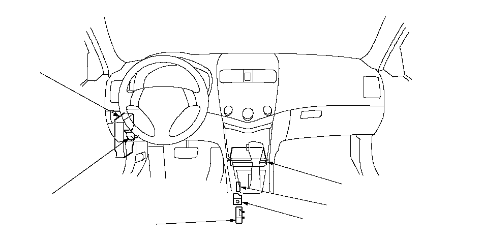 SHIFT LOCK SOLENOIDPOWERTRAIN CONTROL
 MODULE (PCM)DATA LINK
CONNECTOR (DLC)PARK PIN SWITCHTRANSMISSION GEAR SELECTION SWITCHUNDER-DASH
FUSE/RELAY BOXNOTE: The illustration shows LHD model; RHD is symmetrical.
Engine Compartmant:
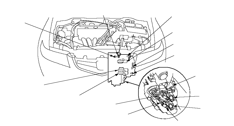 COUNTERSHAFT SPEED SENSORTRANSMISSION RANGE SWITCH2ND CLUTCH
TRANSMISSION FLUID
PRESSURE SWITCH MAINSHAFT SPEED
SENSORA/T CLUTCH PRESSURE
CONTROL SOLENOID VALVE C3RD CLUTCH
TRANSMISSION FLUID
PRESSURE SWITCHATF TEMPERATURE SENSORSHIFT SOLENOID
VALVE CA/T CLUTCH PRESSURE
CONTROL SOLENOID VALVE BA/T CLUTCH PRESSURE
CONTROL SOLENOID VALVE ASHIFT SOLENOID
VALVE BSHIFT SOLENOID
VALVE ASHIFT SOLENOID
VALVE ESHIFT SOLENOID
VALVE DNOTE: The illustration shows LHD model; RHD is similar.
Shift Control
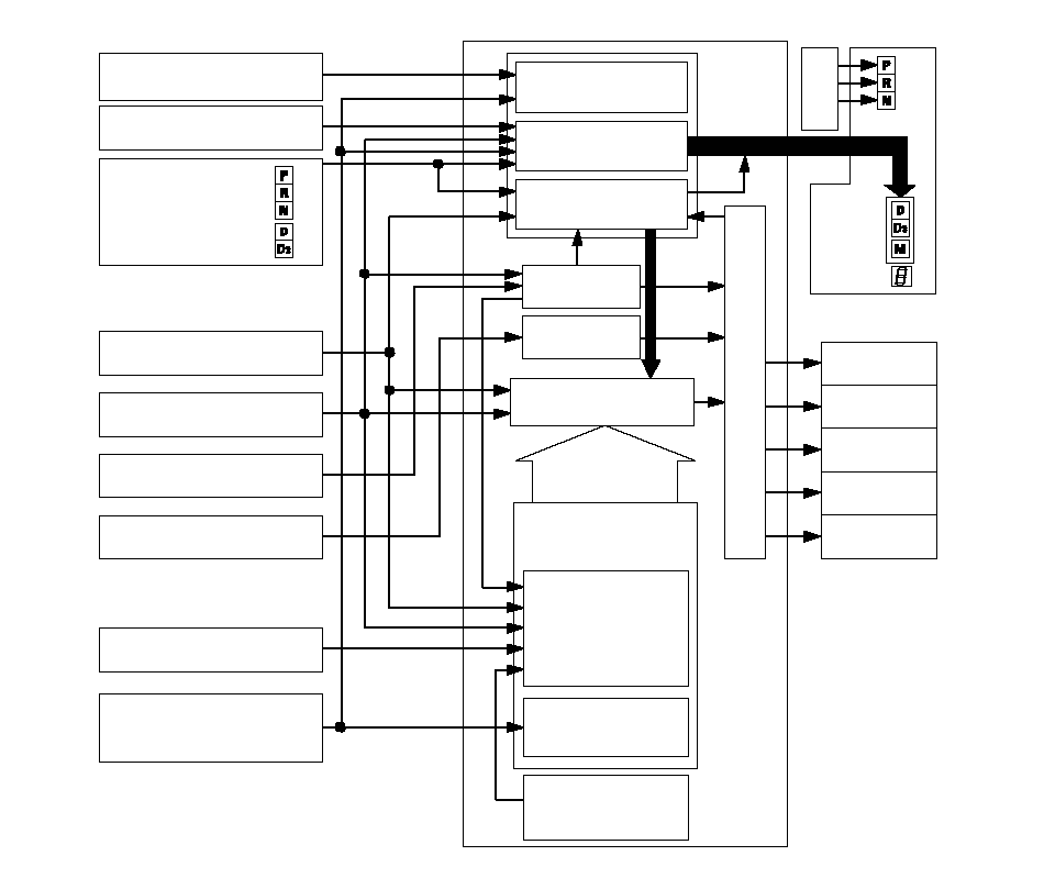
The PCM instantly determines which gear should be selected by various signals sent from sensors and switches, and it actuates the shift solenoid valves A, B, C, D, and E to control shifting.
Also, a grade logic control system has been adopted to control shifting in [D] and [D3] positions. The PCM compares actual driving conditions with memorized driving conditions, based on the input from the throttle position sensor, the engine coolant temperature sensor, the barometric pressure sensor, the brake pedal position switch signal, and the shift lever position signal, to control shifting while the vehicle is ascending or descending a slope.
 Transmission
Range
Switch SignalPCMA/T Gear
Position
IndicatorGauge AssemblyBrake Pedal Position
Switch SignalEngine RPM
controlEngine RPM SignalTransmission Gear
Selection Switch SignalThrottle Position
Sensor SignalCountershaft Speed
Sensor SignalMainshaft Speed
Sensor SignalATF Temperature
Sensor SignalEngine Coolant
Temperature
Sensor SignalShift position
controlFail-safe controlActual Driving
Shift PositionRead of ATF
TemperatureMaster Target of
Shifting PositionCorrection of Data
Selection of
shifting modeGrade Logic ControlCalculation of
gradientCorrection of engine
coolant temperature
sensor signal dataBarometric
Pressure
Sensor Signal·Ascending modeDescending mode·MultiplexShift
IndicatorShift Solenoid
Valve AShift Solenoid
Valve BShift Solenoid
Valve CShift Solenoid
Valve DShift Solenoid
Valve E../../PNG/CO000001.BMP../../PNG/CO000002.BMP../../PNG/CO000003.BMP
Electronic Control System (cont'd)
The PCM turns the shift solenoid valves A, B, C, D, and E ON and OFF to control shifting transmission gear. The combination of driving signals to shift solenoid valves A, B, C, D, and E are shown in table below.
| Position | Gear position | Shift solenoid valves | ||||
|---|---|---|---|---|---|---|
| A | B | C | D | E | ||
| [D],[D3],[M] | Shifting from [N] position | OFF | ON | ON | OFF | OFF |
| Stays in 1st | ON | ON | ON | OFF | OFF | |
| Shifting gears between 1st and 2nd | OFF | ON | ON | OFF | OFF | |
| Stays in 2nd | OFF | ON | OFF | ON | OFF | |
| Shifting gears between 2nd and 3rd | OFF | ON | ON | ON | OFF | |
| Stays in 3rd | OFF | OFF | ON | OFF | OFF | |
| [D],[M] | Shifting gears between 3rd and 4th | OFF | OFF | OFF | OFF | OFF |
| Stays in 4th | ON | OFF | OFF | OFF | OFF | |
| Shifting gears between 4th and 5th | ON | OFF | OFF | ON | OFF | |
| Stays in 5th | ON | OFF | ON | ON | OFF | |
| [R] | Shifting from [P] and [N] position | OFF | ON | OFF | OFF | ON |
| Stays in reverse | ON | ON | OFF | OFF | ON | |
| Reverse inhibit | ON | ON | OFF | OFF | OFF | |
| [P] | Park | OFF | ON | OFF | OFF | ON |
| [N] | Neutral | OFF | ON | ON | OFF | OFF |
Grade Logic Control
Ascending Control
When the PCM determines that the vehicle is climbing a hill in [D] and [D3] positions, the system extends the engagement area of 2nd, 3rd, and 4th gears to prevent the transmission from frequently shifting between 2nd and 3rd gears, between 3rd and 4th gears, and between 4th and 5th gears, so the vehicle can run smooth and have more power when needed.
Shift schedules stored in the PCM between 2nd and 3rd gears, between 3rd and 4th gears, and between 4th and 5th gears, enable it to automatically select the most suitable gear according to the magnitude of a gradient.
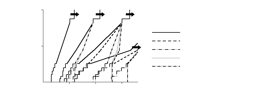 100%50062 mph (100 km/h)Vehicle speedASCENDING MODE: Upshift Schedule: FLAT ROAD MODE: GRADUAL ASCENDING MODE: MEDIUM ASCENDING MODE: STEEP ASCENDING MODE3RD4TH4TH2ND1ST5TH: HEAVY STEEP ASCENDING MODE../../PNG/CO000004.BMP
Descending Control
When the PCM determines that the vehicle is going down a hill in [D] and [D3] positions, the shift-up speed from 4th to 5th gear, from 3rd to 4th gear, and from 2nd to 3rd gear (when the throttle is closed) becomes faster than the set speed for flat road driving to widen the 4th gear, 3rd gear, and 2nd gear driving area. This, in combination with engine braking from the deceleration lock-up, achieves smooth driving when the vehicle is descending. There are three descending modes with different 4th gear driving areas, 3rd gear driving areas, and 2nd gear driving areas according to the magnitude of a gradient stored in the PCM. When the vehicle is in 5th gear or 4th gear, and you are decelerating when you are applying the brakes on a steep hill, the transmission will downshift to lower gear. When you accelerate, the transmission will then return to a higher gear.
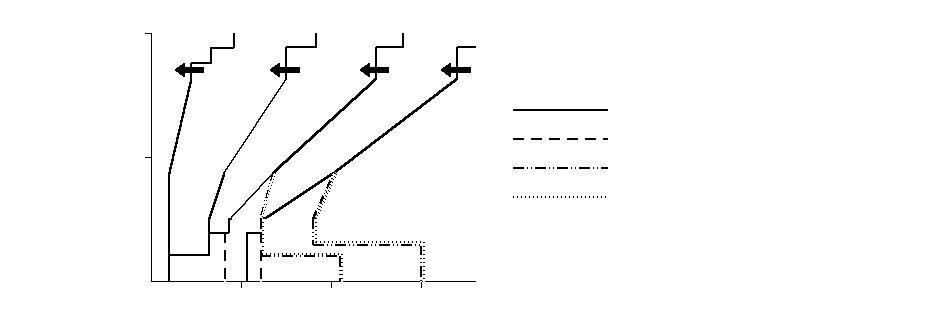 100%500DECENDING MODE: Downshift Schedule: FLAT ROAD MODE: GRADUAL DESCENDING MODE: MEDIUM DESCENDING MODE: STEEP DESCENDING MODE3RD4TH62 mph (100 km/h)Vehicle speed2ND1ST5TH../../PNG/CO000005.BMP
Electronic Control System (cont'd)
Clutch Pressure Control
The PCM actuates the A/T clutch pressure control solenoid valves A, B and C to control the clutch pressure. When shifting between lower and higher gears, the clutch pressure regulated by the A/T clutch pressure control solenoid valves A, B, and C engages and disengages the clutch smoothly.
The PCM recieves input signals from the various sensors and switches, performs processing data, and outputs a current to the A/T clutch pressure control solenoid valves A, B, and C.
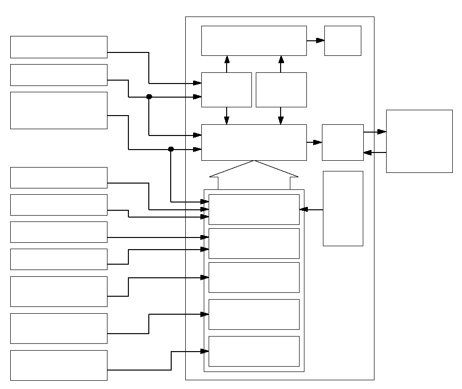 Mainshaft Speed
Sensor SignalCountershaft Speed
Sensor SignalTrottle Position
Sensor SignalManifold Absolute
Pressure Sensor SignalEngine RPM SignalEngine Coolant
Temperature
Sensor SignalActual
driving shift
positionDecision of
shifting
modeIgnition timing
requirementPGM-FI
Control
SystemMaster Target of
Controlling CurrentCurrent
feedbackCorrection of
DataCorrection of engine
torque signal dataCorrection of engine
coolant temperature
sensor dataCorrection of sequential
sportshift mode position
driving condition dataA/T Clutch
Pressure Control
Solenoid Valves
A, B and CPCM2nd Clutch Transmission Fluid
Pressure Switch Signal3rd Clutch Transmission Fluid
Pressure Switch SignalATF Temperature
Sensor SignalTransmission Gear
Selection Switch SignalCorrection of hydraulic
pressure application
timingCorrection of ATF
temperature sensor
signal dataBarometric
Pressure
Sensor
Signal
Lock-up Control
The shift solenoid valve E controls the hydraulic pressure to switch the lock-up shift valve and lock-up ON and OFF.
The PCM actuates the shift solenoid valve E and the A/T clutch pressure control solenoid valve A to control the torque converter clutch lock-up. When the shift solenoid valve E is turned ON, the condition of the lock-up starts.
The A/T clutch pressure control solenoid valve A regulates and applies the hydraulic pressure to the lock-up control valve to control the amount of the lock-up.
The lock-up mechanism operates in 2nd, 3rd, 4th, and 5th gears in [D] position, 2nd and 3rd gears in [D3] position, and 3rd, 4th, and 5th gears in [M] position.
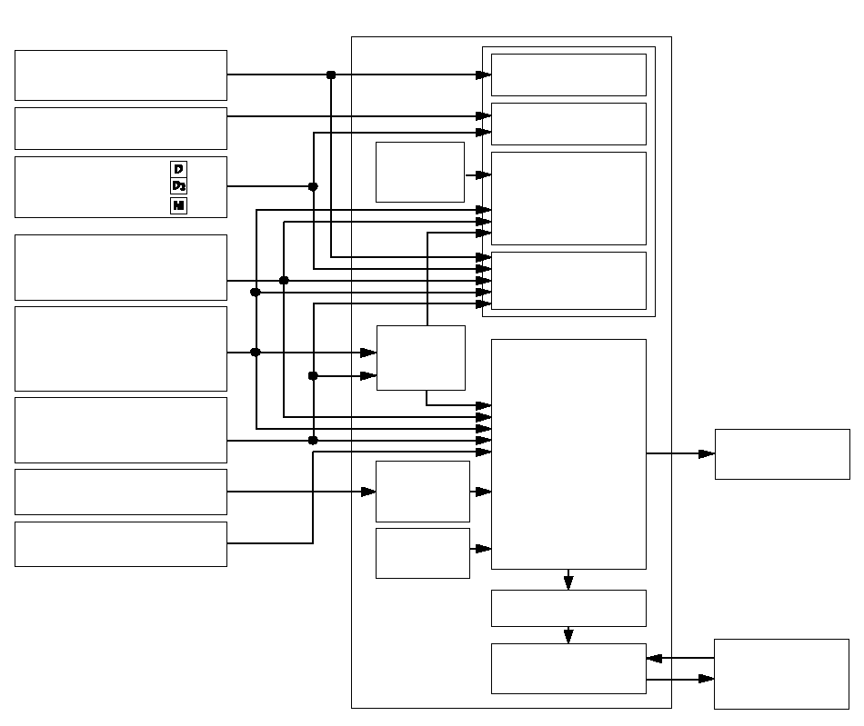 Lock-up Control·Lock-up ON/OFF
controlLock-up condition
control·PCMEngine Coolant
Temperature
Sensor SignalTransmission
Range
Switch SignalThrottle Position
Sensor SignalMainshaft Speed
Sensor SignalCountershaft Speed
Sensor SignalFail-safe controlTransmission Gear
Selection Shift Switch
SignalATF Temperature
Sensor SignalEngine RPM SignalEngine coolant
temperature controlShifting position
controlBarometric
Pressure
Sensor
SignalActual
driving
shift
positionCorrection
of ATF
temperature
sensor dataDriving shift
position
informationCurrent feedbackMaster Target of
Controlling CurrentShift Solenoid
Valve EA/T Clutch
Pressure
Control Solenoid
Valve AGradient control
by magnitude
Electronic Control System (cont'd)
PCM Electrical Connections
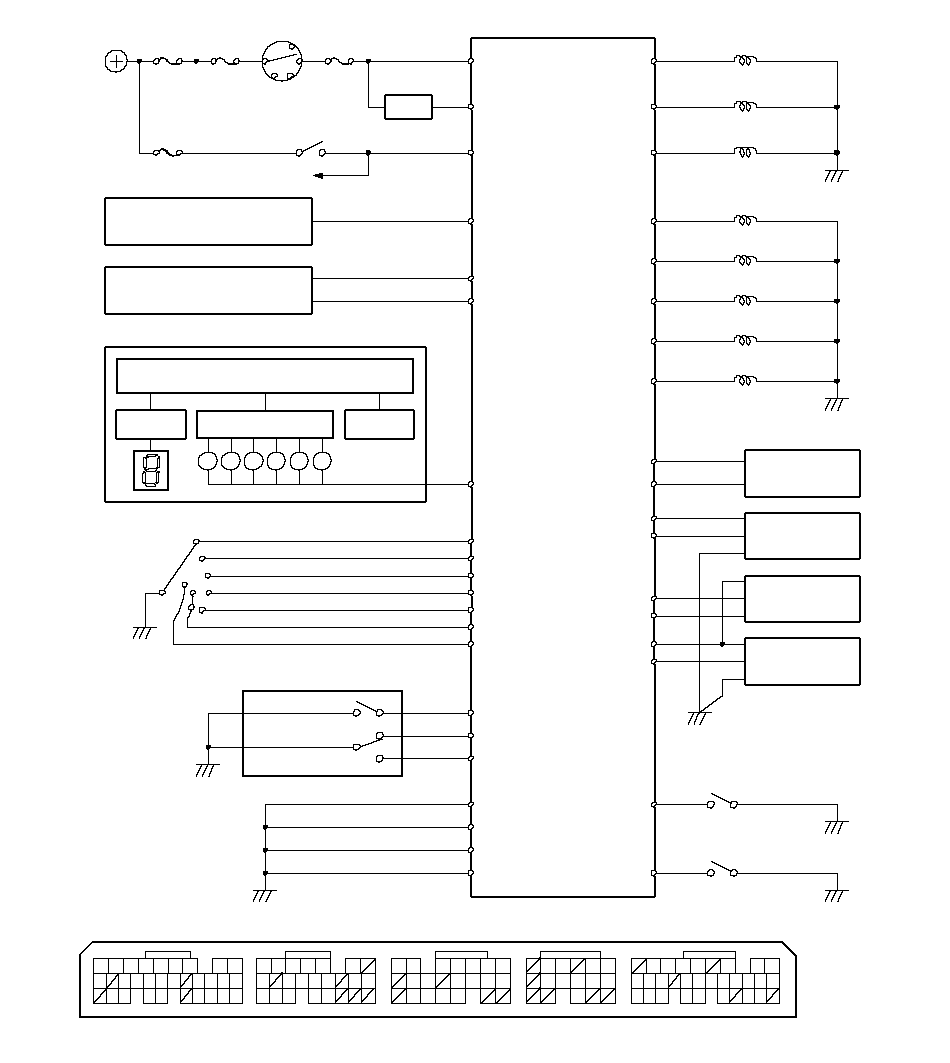 SELECTION SWITCHTRANSMISSION GEAR(19)(15)(8)932(20)(19)(16)(12)(11)10(29)28(26)(25)A23SG2SHIFT SWITCHMANUAL MODE SWITCHS-DND9D3S-UPS-MODED2Indicator DriverShift Position(10)On some types(14)3RD CLUTCH2ND CLUTCHSENSORMAINSHAFTSPEEDC5SH DSHIFT SOLENOIDVALVE DLS C+C7VALVE CCONTROL SOLENOIDA/T CLUTCH PRESSURELS B+C15A/T CLUTCH PRESSURECONTROL SOLENOIDVALVE BVALVE ACONTROL SOLENOIDA/T CLUTCH PRESSURETRANSMISSION FLUIDPRESSURE SWITCHSOLENOIDSHIFT LOCKE2SLSGAUGE CONTROL MODULEMET INHD10D3(17)1211(11)20531181413ATP FWDC1830(27)2021158(12)181881652M13A (31P)B (24P)C (22P)E (31P)PCM Connector Terminal Locations262297431618292423121091514412672117151365432823243021201915(12)10123456793172516510D (17P)19SH EVALVE ESHIFT SOLENOIDSH CVALVE CSHIFT SOLENOIDSH BSHIFT SOLENOIDVALVE BA21PRESSUREABSOLUTEMANIFOLDSENSORSG1A24A30VCC2A20COUNTERSHAFTSPEEDSENSORATFA18NCNMC19VCC1PRESSURE SWITCH TRANSMISSION FLUIDLG2A8A9LG1A4PG2PG1A3D6ATP PCRUISE CONTROL UNITIG1BATTERYLS A+C1IG1E9PCMC6SH AD12CRSBRAKE LIGHTE22BK SWC4C9ATP DATP RD5RDPNSWITCHRANGETRANSMISSIONNRPC17C12ATP RVSOP2SWC13IGNITION SWITCHK-LINEE23CPUD3ATP D3SCSE29POSITION SWITCHBRAKE PEDALC14ATFTTEMPERATURESENSORVALVE ASHIFT SOLENOIDBATDATA LINK CONNECTORDC3C2C10OP3SWC20ATP NA/T Indicator DriverDimmingCancel CircuitMAP
PCM Inputs and Outputs
The PCM terminal voltage and measuring conditions are shown for the connector terminals that are related to the A/T control system. The other terminal voltage and measuring conditions are described in Fuel and Emission.
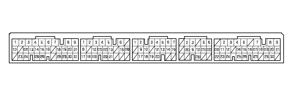 PCM Connector Terminal Locations
| Terminal Number | Wire Color | Signal | Description | Measuring Conditions/Terminal Voltage |
|---|---|---|---|---|
| A2 | YEL/BLK | IGP2 | Power supply circuit from main relay | With ignition switch ON (II): Battery voltage With ignition switch OFF: 0 V |
| A3 | YEL/BLK | IGP1 | Power supply circuit from main relay | With ignition switch ON (II): Battery voltage With ignition switch OFF: 0 V |
| A4 | BLK | PG2 | Ground | Less than 1.0 V at all times |
| A5 | BLK | PG1 | Ground | Less than 1.0 V at all times |
| A8 | BRN/YEL | LG2 | Ground | Less than 1.0 V at all times |
| A9 | BRN/YEL | LG1 | Ground | Less than 1.0 V at all times |
| A18 | BLK/BLU | NC | Countershaft speed sensor signal input | With ignition switch ON (II): 0 V or about 5 V While driving: About 2.5 V |
| A20 | YEL/BLU | VCC2 | Power supply circuit for sensors | With ignition switch ON (II): About 5 V With ignition switch OFF: 0 V |
| A21 | YEL/RED | VCC1 | Power supply circuit for sensors | With ignition switch ON (II): About 5 V With ignition switch OFF: 0 V |
| A23 | GRN/YEL | SG2 | Sensor ground | Less than 1.0 V at all times |
| A24 | GRN/WHT | SG1 | Sensor ground | Less than 1.0 V at all times |
Electronic Control System (cont'd)
PCM Inputs and Outputs (cont'd)
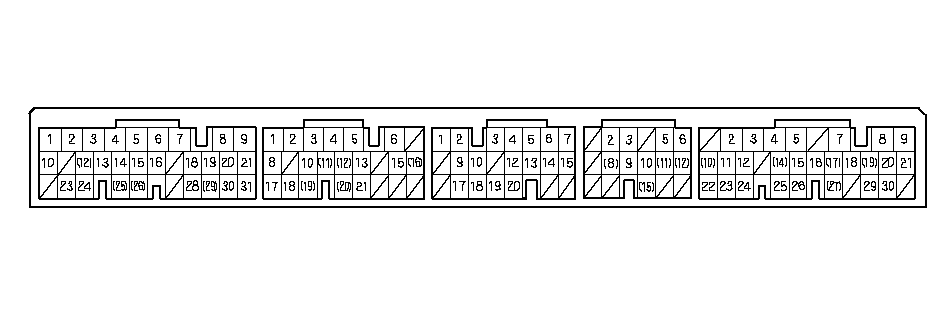 PCM Connector Terminal Locations
| Terminal Number | Wire Color | Signal | Description | Measuring Condition/Terminal Voltage |
|---|---|---|---|---|
| C1 | RED/BLK | LS A+ | A/T clutch pressure control solenoid valve A power supply positive electrode | With ignition switch ON (II): Pulsing signal |
| C2 | GRN | SH C | Shift solenoid valve C control | Battery voltage in these positions:
|
| C3 | YEL | SH E | Shift solenoid valve E control | Battery voltage in these positions:
|
| C4 | GRN/WHT | SH B | Shift solenoid valve B control | Battery voltage in these positions:
|
| C5 | GRN/RED | SH D | Shift solenoid valve D control | Battery voltage in these positions:
|
| C6 | BLU/BLK | SH A | Shift solenoid valve A control | Battery voltage in these positions:
|
| C7 | BLU/YEL | LS C+ | A/T clutch pressure control solenoid valve C power supply electrode | With ignition switch ON (II): Pulsing signal |
| Terminal Number | Wire Color | Signal | Description | Measuring Condition/Terminal Voltage |
|---|---|---|---|---|
| C9 | RED | ATP D3 | Transmission range switch [D3] position signal input | In the [D3] position: 0 V In other than the [D3] position: Battery voltage |
| C10 | BLU/WHT | OP3SW | 3rd clutch transmission fluid pressure switch signal input | With ignition switch ON (II): About 5 V With 3rd clutch pressure: 0 V |
| C12 | RED/WHT | ATP RVS | Transmission range switch RVS ([R] position) signal input | In [R] position: 0 V In other than the [R] position: Battery voltage |
| C13 | BLU/RED | OP2SW | 2nd clutch transmission fluid pressure switch signal input | With ignition switch ON (II): About 5 V With 2nd clutch pressure: 0 V |
| C14 | RED/YEL | ATFT | ATF temperature sensor signal input | With ignition switch ON (II): 0.2 V-4.8 V With ignition switch OFF: 0 V |
| C15 | BRN/WHT | LS B+ | A/T clutch pressure control solenoid valve B power supply electrode | With ignition switch ON (II): Pulsing signal |
| C17 | YEL/GRN | ATP D | Transmission range switch [D] position signal input | In the [D] position: 0 V In other than the [D] position: Battery voltage |
| C18 | BLU/YEL | ATP FWD | Transmission range switch [D] and [D3] position signals input | In the [D] and [D3] positions: 0 V In other than the [D] and [D3] positions: Battery voltage |
| C19 | WHT/RED | NM | Mainshaft speed sensor signal input | With ignition switch ON (II): 0 V or about 5 V With engine at idling in [N] position: About 2.5 V |
| C20 | RED/BLK | ATP N | Transmission range switch [N] position signal input | In the [N] position: 0 V In other than the [N] position: Battery voltage |
Electronic Control System (cont'd)
PCM Inputs and Outputs (cont'd)
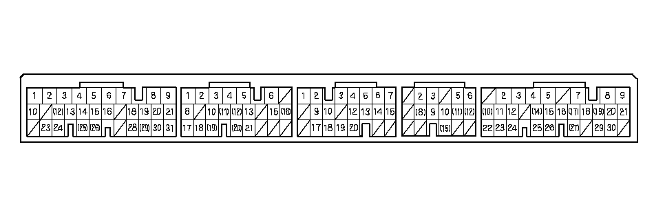 PCM Connector Terminal Locations
| Terminal Number | Wire Color | Signal | Description | Measuring Conditions/Terminal Voltage |
|---|---|---|---|---|
| D2 | BRN | S-MODE | Transmission gear selection switch downshift switch signal input | In [M] position: 0 V In other than [M] position: About 5V |
| D3 | WHT | S-UP | Transmission gear selection switch upshift switch signal input | In [M] position:
|
| D5 | WHT | ATP R | Transmission range switch [R] position input | In the [R] position: 0 V In other than the [R] position: Battery voltage |
| D6 | BLU | ATP P | Transmission range switch [P] position input | In the [P] position: 0 V In other than the [P] position: Battery voltage |
| D9 | ORN | S-DN | Transmission gear selection switch downshift switch signal input | In [M] position:
|
| D10 | LT GRN | METINH | A/T gear position indicator control signal output | With ignition switch ON (II): Battery voltage |
| D11 | PNK | ATCCFWD | Transmission range switch [D] and [D3] position signals output to cruise control unit | In the [D] and [D3] positions: 0 V In other than the [D] and [D3] position: Battery voltage |
| D12 | BLU/BLK | CCS | Downshift signal input from cruise control unit | When cruise control is used: Pulsing signal |
| Terminal Number | Wire Color | Signal | Description | Measuring Conditions/Terminal Voltage |
|---|---|---|---|---|
| E2 | GRN | SLS | Shift lock solenoid control (ground side) | With ignition switch ON (II), in the [P] position, brake pedal pressed, and accelerator released: 0 V |
| E9 | BLK/YEL | IG1 | Power supply circuit for solenoid valves | With ignition switch ON (II): Battery voltage With ignition switch OFF: 0 V |
| E11 | WHT | CAN H | F-CAN communication with network | With ignition switch ON (II): Pulsing signal |
| E22 | WHT/BLK | BKSW | Brake pedal position switch signal input | Brake pedal pressed: Battery voltage Brake pedal released: 0 V |
| E23 | LT BLU | K-LINE | Communication line PCM-to-DLC | With ignition switch ON (II): Battery voltage |
| E24 | RED | CAN L | F-CAN communication with network | With ignition switch ON (II): Pulsing signal |
| E29 | BRN | SCS | Detects service check signal | With the SCS shorted with the PGM tester or the HDS: About 0 V With the SCS open: About 5 V |
Hydraulic Controls
Valve Bodies
The valve body includes the main valve body, the regulator valve body, and the servo body. The ATF pump is driven by splines on the left end of the torque converter which is attached to the engine. Fluid flows through the regulator valve to maintain specified pressure through the main valve body to the manual valve, directing pressure to the shift valves and to each of the clutches via the solenoid valves. The shift solenoid valves A, B, C, D, and E are bolted on the servo body. The A/T clutch pressure control solenoid valves A, B, and C are mounted on the outside of the transmission housing.
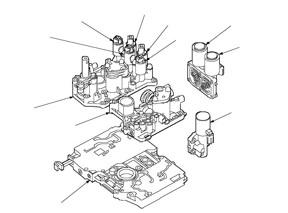 SHIFT SOLENOID
VALVE ASHIFT SOLENOID
VALVE BSHIFT SOLENOID
VALVE CSHIFT SOLENOID
VALVE DSHIFT SOLENOID
VALVE ESERVO BODYA/T CLUTCH PRESSURE
CONTROL SOLENOID
VALVE BA/T CLUTCH PRESSURE
CONTROL SOLENOID
VALVE CA/T CLUTCH PRESSURE
CONTROL SOLENOID
VALVE AREGULATOR
VALVE BODYMAIN VALVE BODY
Hydraulic Controls (cont'd)
Main Valve Body
The main valve body contains the manual valve, the shift valves A, B, C, and E, the relief valve, the lock-up control valve, the cooler check valve, the servo control valve, and the ATF pump gears. The primary function of the main valve body is to switch fluid pressure on and off and to control hydraulic pressure going to the hydraulic control system.
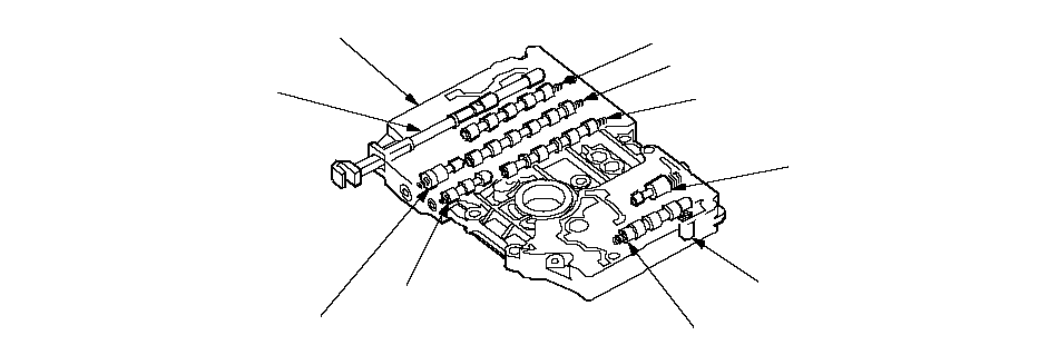 SHIFT VALVE AMAIN VALVE BODYSHIFT VALVE BSHIFT VALVE CCOOLER CHECK VALVELOCK-UP CONTROL VALVESHIFT VALVE ESERVO CONTROL VALVERELIEF VALVEMANUAL VALVE
Regulator Valve Body
The regulator valve body contains the regulator valve, the torque converter check valve, lock-up shift valve, and the 1st and 3rd accumulators.
 REGULATOR VALVE BODYLOCK-UP SHIFT VALVEREGULATOR VALVETORQUE CONVERTER
 CHECK VALVE
Regulator Valve
The regulator valve maintains a constant hydraulic pressure from the ATF pump to the hydraulic control system, while also furnishing fluid to the lubrication system and torque converter. The fluid from the ATF pump flows through B and C. Fluid entering from B flows through the valve orifice to the A cavity. This pressure of the A cavity pushes the regulator valve to the right side, and this movement of the regulator valve uncovers the fluid port to the torque converter and the relief valve. The fluid flows out to the torque converter and the relief valve, and the regulator valve moves to the left side. According to the level of the hydraulic pressure through B, the position of the regulator valve changes, and the amount of fluid from C through torque converter also changes. This operation is continued, maintaining the line pressure.
NOTE: When used, ‘‘left'' or ‘‘right'' indicates direction on the illustration below.
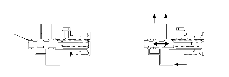 To TORQUE
 CONVERTERFrom ATF PUMPTo LUBRICATIONCBAREGULATOR VALVEORIFICE
Increases in hydraulic pressure according to torque are performed by the regulator valve using stator torque reaction. The stator shaft is splined with the stator in the torque converter, and its arm end contacts the regulator spring cap. When the vehicle is accelerating or climbing (Torque Converter Range), stator torque reaction acts on the stator shaft, and the stator arm pushes the regulator spring cap in the direction of the arrow in proportion to the reaction. The stator reaction spring compresses, and the regulator valve moves to increase the line pressure which is regulated by the regulator valve. The line pressure reaches its maximum when the stator torque reaction reaches its maximum.
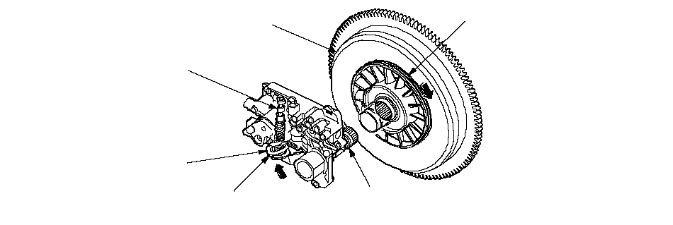 REGULATOR VALVETORQUE CONVERTERSTATORSTATOR SHAFTSTATOR SHAFT
ARM ENDREGULATOR
SPRING CAP
Hydraulic Controls (cont'd)
Servo Body
The servo body contains the servo valve, the shift valve D, accumulators for 2nd, 4th, and 5th, and shift solenoid valves for A, B, C, D, and E.
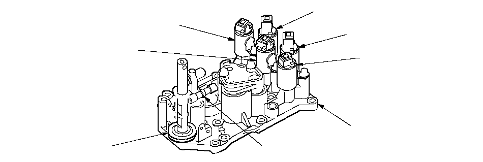 SHIFT SOLENOID
VALVE ASHIFT SOLENOID
VALVE BSHIFT SOLENOID
VALVE CSHIFT SOLENOID
VALVE DSHIFT SOLENOID
VALVE ESERVO BODYSERVO VALVESHIFT VALVE D
Accumulator
The accumulators are located in the regulator valve body and the servo body. The regulator valve body contains the 1st and 3rd accumulators, and the servo body contains the 2nd, 4th, and 5th accumulators.
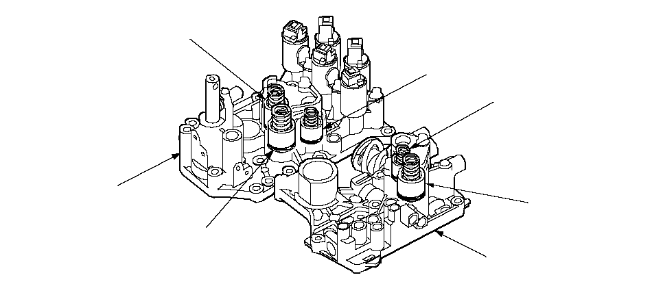 5TH ACCUMULATOR3RD ACCUMULATOR1ST ACCUMULATORREGULATOR
VALVE BODY4TH ACCUMULATOR2ND ACCUMULATORSERVO BODY
Hydraulic Flow
Distribution of Hydraulic Pressure
As the engine turns, the ATF pump starts to operate. Automatic transmission fluid (ATF) is drawn through the ATF strainer (filter) and discharged into the hydraulic circuit. Then, ATF flowing from the ATF pump becomes line pressure that's regulated by the regulator valve. Torque converter pressure from the regulator valve enters the torque converter through the lock-up shift valve, and it is discharged from the torque converter. The torque converter check valve prevents torque converter pressure from rising.The PCM controls the shift solenoid valves ON and OFF. The shift valve intercepts line pressure from the ATF pump via the manual valve when the shift solenoid valve is OFF. When the shift solenoid valve is turned ON, line pressure changes to shift solenoid valve pressure at the shift solenoid valve, then the solenoid valve pressure flows to the shift valve. Applying shift solenoid pressure to the shift valves moves the position of the shift valve, and switches the port of the hydraulic circuit. The PCM also controls A/T clutch pressure control solenoid valves A, B, and C. The A/T clutch pressure control solenoid valves regulate hydraulic pressure, and apply the pressure to the clutches for engaging smoothly. The clutches are received optimum clutch pressure which is regulated by the A/T clutch pressure control solenoid valves for comfortable driving and shifting under all conditions.
| PORT NO. | DESCRIPTION OF PRESSURE | PORT NO. | DESCRIPTION OF PRESSURE |
|---|---|---|---|
| 1 | LINE | SB | SHIFT SOLENOID VALVE B |
| 3 | LINE | SC | SHIFT SOLENOID VALVE C |
| 3' | LINE | SD | SHIFT SOLENOID VALVE D |
| 4 | LINE | SE | SHIFT SOLENOID VALVE E |
| 4' | LINE | 10 | 1ST CLUTCH |
| 4'' | LINE | 20 | 2ND CLUTCH |
| 7 | LINE | 30 | 3RD CLUTCH |
| 1A | LINE or A/T CLUTCH PRESSURE CONTROL SOLENOID VALVE A | 40 | 4TH CLUTCH |
| 1B | LINE | 50 | 5TH CLUTCH |
| 3A | LINE | 55 | A/T CLUTCH PRESSURE CONTROL SOLENOID VALVE A |
| 3B | LINE | 55' | A/T CLUTCH PRESSURE CONTROL SOLENOID VALVE A |
| 3C | LINE | 56 | A/T CLUTCH PRESSURE CONTROL SOLENOID VALVE B |
| 5A | LINE | 57 | A/T CLUTCH PRESSURE CONTROL SOLENOID VALVE C |
| 5B | LINE | 90 | TORQUE CONVERTER |
| 5C | LINE | 91 | TORQUE CONVERTER |
| 5D | LINE | 92 | TORQUE CONVERTER |
| 5E | LINE or A/T CLUTCH PRESSURE CONTROL SOLENOID VALVE B | 93 | ATF COOLER |
| 5F | LINE or A/T CLUTCH PRESSURE CONTROL SOLENOID VALVE A or B | 94 | TORQUE CONVERTER |
| 5G | A/T CLUTCH PRESSURE CONTROL SOLENOID VALVE B | 95 | LUBRICATION |
| 5H | A/T CLUTCH PRESSURE CONTROL SOLENOID VALVE C | 96 | TORQUE CONVERTER |
| 5J | A/T CLUTCH PRESSURE CONTROL SOLENOID VALVE C | 97 | TORQUE CONVERTER |
| 5K | A/T CLUTCH PRESSURE CONTROL SOLENOID VALVE C | 99 | SUCTION |
| 5L | A/T CLUTCH PRESSURE CONTROL SOLENOID VALVE C | X | DRAIN |
| 5N | A/T CLUTCH PRESSURE CONTROL SOLENOID VALVE C | HX | HIGH POSITION DRAIN |
| SA | SHIFT SOLENOID VALVE A | AX | AIR DRAIN |
Hydraulic Flow (cont'd)
[N] Position
The PCM controls the shift solenoid valves. The conditions of the shift solenoid valves and positions of the shift valves are as follows:
- Shift solenoid valve A: OFF Shift valve A keeps in right side
- Shift solenoid valve B: ON Shift valve B moves to left side
- Shift solenoid valve C: ON Shift valve C moves to left side
- Shift solenoid valve D: OFF Shift valve D keeps in left side
- Shift solenoid valve E: OFF Shift valve E keeps in left side
NOTE: When used, ‘‘left'' or ‘‘right'' indicates direction on the hydraulic circuit.
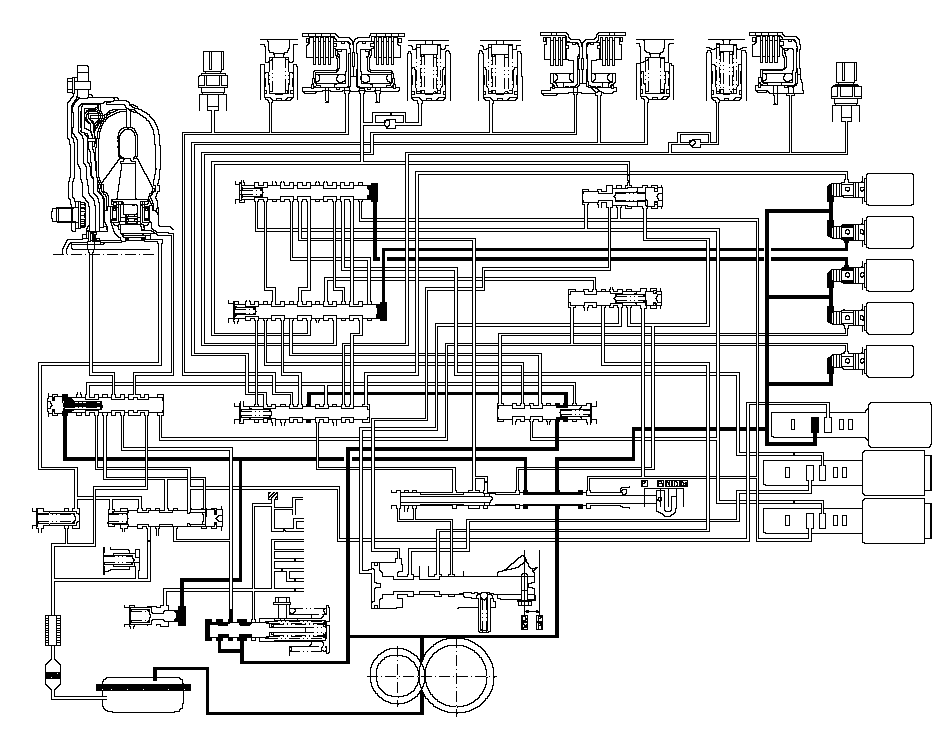 TORQUE
CONVERTER3RD CLUTCH
TRANSMISSION FLUID
PRESSURE
SWITCH3RD
ACCUMULATOR3RD
CLUTCH1ST
CLUTCH1ST
ACCUMULATOR4TH
ACCUMULATOR4TH
CLUTCH5TH
CLUTCH5TH
ACCUMULATOR2ND
ACCUMULATOR2ND
CLUTCH2ND CLUTCH
TRANSMISSION FLUID
PRESSURE
SWITCH303095301095104040505020952020919094LOCK-UP
SHIFT
VALVEX55'94917559692SE93XXX5AXX565E575H5C5B5G4SCSHIFT
VALVE
CSHIFT
VALVE
BX5H5B5G3C5E5CSBX5N5L5JX10405FSHIFT
VALVE
AX5N5030X1A1BX55'5FSA10344'X57SERVO CONTROL VALVESHIFT VALVE E3CXSEX3B3'345K5K20XSDX5L5J1A55'57X1XSHIFT
VALVE
DTORQUE
CONVERTER
CHECK
VALVEX939090X939096X925597COOLER
CHECK
VALVEX93ATF
COOLERLOCK-UP
CONTROL
VALVE957XXRELIEF VALVE99AXHXAXHXIDLE
SHAFTIDLE GEARMAINSHAFTCOUNTERSHAFTFINAL DRIVE
GEARSECONDARY
SHAFT929511REGULATOR VALVESERVO VALVEATF PUMP3'4'4''X3B3A3A3AX1B5A5A3714MANUAL VALVESHIFT
SOLENOID
VALVESSAA: OFFB: ONC: OND: OFFE: OFFABCXXXXXSBSCSDSE55X1XAX56X4''XAX574XAXXA/T CLUTCH PRESSURE
CONTROL SOLENOID VALVES111
[D] Position: 1st gear shifting from [N] position
Shift solenoid valves remain the same as in the [N] position, when shifting to the [D] position from [N]. The manual valve is moved to the [D] position, and switches the port of line pressure (4) leading to the A/T clutch pressure control solenoid valves. Hydraulic pressure line to the 1st clutch from the A/T clutch pressure control solenoid valve A is created as shift solenoid valve A is OFF, B and C keep ON. A/T clutch pressure control solenoid valve A pressure (55) changes to 1st clutch pressure (10) at the shift valve B, and flows to the 1st clutch. The 1st clutch is engaged gently when shifting to the [D] position from [N].
NOTE: When used, ‘‘left'' or ‘‘right'' indicates direction on the hydraulic circuit.
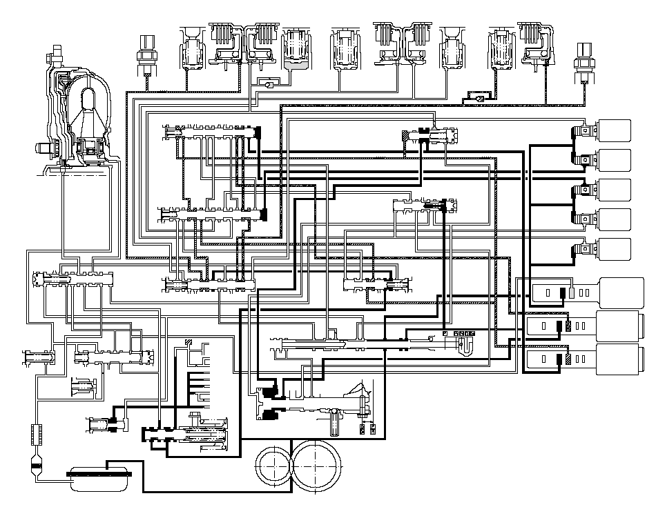 TORQUE
CONVERTER3RD CLUTCH
TRANSMISSION FLUID
PRESSURE
SWITCH3RD
ACCUMULATOR3RD
CLUTCH1ST
CLUTCH1ST
ACCUMULATOR4TH
ACCUMULATOR4TH
CLUTCH5TH
CLUTCH5TH
ACCUMULATOR2ND
ACCUMULATOR2ND
CLUTCH2ND CLUTCH
TRANSMISSION FLUID
PRESSURE
SWITCH303095301095104040505020952020919094LOCK-UP
SHIFT
VALVEX55'94917559692SE93XXX5AXX565E575H5C5B5G4SCSHIFT
VALVE
CSHIFT
VALVE
BX5H5B5G3C5E5CSBX5N5L5JX10405FSHIFT
VALVE
AX5N5030X1A1BX55'5FSA10344'X57SERVO CONTROL VALVESHIFT VALVE E3CXSEX3B3'345K5K20XSDX5L5J1A55'57X1XSHIFT
VALVE
DTORQUE
CONVERTER
CHECK
VALVEX939090X939096X925597COOLER
CHECK
VALVEX93ATF
COOLERLOCK-UP
CONTROL
VALVE957XXRELIEF VALVE99AXHXAXHXIDLE
SHAFTIDLE GEARMAINSHAFTCOUNTERSHAFTFINAL DRIVE
GEARSECONDARY
SHAFT929511REGULATOR VALVESERVO VALVEATF PUMP3'4'4''X3B3A3A3AX1B5A5A3714MANUAL VALVESHIFT
SOLENOID
VALVESSAA: OFFB: ONC: OND: OFFE: OFFABCXXXXXSBSCSDSE55X1XAX56X4''XAX574XAXXA/T CLUTCH PRESSURE
CONTROL SOLENOID VALVES111
Hydraulic Flow (cont'd)
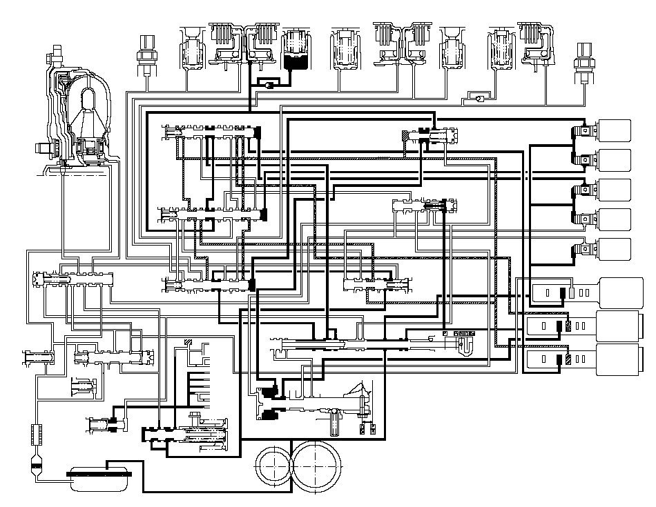
[D] Position: Driving in 1st gear
The PCM turns shift solenoid valves A ON, and keeps B and C ON,and D and E OFF. Shift solenoid valve A pressure (SA) is applied to the right side of the shift valve A. The shift valve A is moved to the left side to uncover the port of line pressure leading to the 1st clutch, and to cover the ports of A/T clutch pressure control solenoid valve pressures.
Fluid flows to the 1st clutch by way of:
Line pressure (1) ® Shift valve D-Line pressure (1A) ® Shift valve A-Line pressure (1B) ® Manual valve-Line pressure (5A) ® Shift valve C-Line pressure (5B) ® Shift valve B-1st clutch pressure (10) ® 1st clutch
The 1st clutch pressure (10) is applied to the 1st clutch, and the 1st clutch is engaged securely.
NOTE: When used, ‘‘left'' or ‘‘right'' indicates direction on the hydraulic circuit.
 TORQUE
CONVERTER3RD CLUTCH
TRANSMISSION FLUID
PRESSURE
SWITCH3RD
ACCUMULATOR3RD
CLUTCH1ST
CLUTCH1ST
ACCUMULATOR4TH
ACCUMULATOR4TH
CLUTCH5TH
CLUTCH5TH
ACCUMULATOR2ND
ACCUMULATOR2ND
CLUTCH2ND CLUTCH
TRANSMISSION FLUID
PRESSURE
SWITCH303095301095104040505020952020919094LOCK-UP
SHIFT
VALVEX55'94917559692SE93XXX5AXX565E575H5C5B5G4SCSHIFT
VALVE
CSHIFT
VALVE
BX5H5B5G3C5E5CSBX5N5L5JX10405FSHIFT
VALVE
AX5N5030X1A1BX55'5FSA10344'X57SERVO CONTROL VALVESHIFT VALVE E3CXSEX3B3'345K5K20XSDX5L5J1A55'57X1XSHIFT
VALVE
DTORQUE
CONVERTER
CHECK
VALVEX939090X939096X925597COOLER
CHECK
VALVEX93ATF
COOLERLOCK-UP
CONTROL
VALVE957XXRELIEF VALVE99AXHXAXHXIDLE
SHAFTIDLE GEARMAINSHAFTCOUNTERSHAFTFINAL DRIVE
GEARSECONDARY
SHAFT929511REGULATOR VALVESERVO VALVEATF PUMP3'4'4''X3B3A3A3AX1B5A5A3714MANUAL VALVESHIFT
SOLENOID
VALVESSAA: ONB: ONC: OND: OFFE: OFFABCXXXXXSBSCSDSE55X1XAX56X4''XAX574XAXXA/T CLUTCH PRESSURE
CONTROL SOLENOID VALVES111
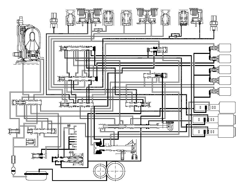
[D] Position: Shifting between 1st gear and 2nd gear
As the speed of the vehicle reaches the prescribed value, the PCM turns shift solenoid valve A OFF, and keeps B and C ON, and D and E OFF. Shift solenoid valve A pressure (SA) in the right side of the shift valve A is released. The shift valve A is moved to the right side to uncover the ports of A/T clutch pressure control solenoid valves pressures leading to the 1st and 2nd clutches. The PCM controls the A/T clutch pressure control solenoid valves to regulate hydraulic pressure. A/T clutch pressure control solenoid valve A pressure (55) changes to 1st clutch pressure (10) at the shift valve B, and A/T clutch pressure control solenoid valve B pressure (56) changes to 2nd clutch pressure (20) at the shift valve A. The 1st and 2nd clutches are engaged gently.
NOTE: When used, ‘‘left'' or ‘‘right'' indicates direction on the hydraulic circuit.
 TORQUE
CONVERTER3RD CLUTCH
TRANSMISSION FLUID
PRESSURE
SWITCH3RD
ACCUMULATOR3RD
CLUTCH1ST
CLUTCH1ST
ACCUMULATOR4TH
ACCUMULATOR4TH
CLUTCH5TH
CLUTCH5TH
ACCUMULATOR2ND
ACCUMULATOR2ND
CLUTCH2ND CLUTCH
TRANSMISSION FLUID
PRESSURE
SWITCH303095301095104040505020952020919094LOCK-UP
SHIFT
VALVEX55'94917559692SE93XXX5AXX565E575H5C5B5G4SCSHIFT
VALVE
CSHIFT
VALVE
BX5H5B5G3C5E5CSBX5N5L5JX10405FSHIFT
VALVE
AX5N5030X1A1BX55'5FSA10344'X57SERVO CONTROL VALVESHIFT VALVE E3CXSEX3B3'345K5K20XSDX5L5J1A55'57X1XSHIFT
VALVE
DTORQUE
CONVERTER
CHECK
VALVEX939090X939096X925597COOLER
CHECK
VALVEX93ATF
COOLERLOCK-UP
CONTROL
VALVE957XXRELIEF VALVE99AXHXAXHXIDLE
SHAFTIDLE GEARMAINSHAFTCOUNTERSHAFTFINAL DRIVE
GEARSECONDARY
SHAFT929511REGULATOR VALVESERVO VALVEATF PUMP3'4'4''X3B3A3A3AX1B5A5A3714MANUAL VALVESHIFT
SOLENOID
VALVESSAA: OFFB: ONC: OND: OFFE: OFFABCXXXXXSBSCSDSE55X1XAX56X4''XAX574XAXXA/T CLUTCH PRESSURE
CONTROL SOLENOID VALVES111
Hydraulic Flow (cont'd)
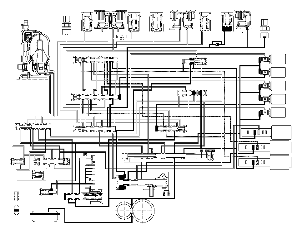
[D] Position: Driving in 2nd gear
The PCM turns shift solenoid valves C OFF, D ON, and keeps A and E OFF, and B ON. Shift solenoid valve C pressure (SC) in the right side of the shift valve C is released. The shift valve C is moved to the right side to switch the ports. This movement covers A/T clutch pressure control solenoid valves pressures to stop at the shift valves C and A, and uncover the port of line pressure leading to the 2nd clutch.
Fluid flows to 2nd clutch by way of:
Line pressure (1) ® Manual valve-Line pressure (4) ® Shift valve C-Line pressure (5E) ® Shift valve B-Line pressure (5F) ® Shift valve A-2nd clutch pressure (20) ® 2nd clutch
The 2nd clutch pressure (20) is applied to the 2nd clutch, and the 2nd clutch is engaged securely.
NOTE: When used, ‘‘left'' or ‘‘right'' indicates direction on the hydraulic circuit.
 TORQUE
CONVERTER3RD CLUTCH
TRANSMISSION FLUID
PRESSURE
SWITCH3RD
ACCUMULATOR3RD
CLUTCH1ST
CLUTCH1ST
ACCUMULATOR4TH
ACCUMULATOR4TH
CLUTCH5TH
CLUTCH5TH
ACCUMULATOR2ND
ACCUMULATOR2ND
CLUTCH2ND CLUTCH
TRANSMISSION FLUID
PRESSURE
SWITCH303095301095104040505020952020919094LOCK-UP
SHIFT
VALVEX55'94917559692SE93XXX5AXX565E575H5C5B5G4SCSHIFT
VALVE
CSHIFT
VALVE
BX5H5B5G3C5E5CSBX5N5L5JX10405FSHIFT
VALVE
AX5N5030X1A1BX55'5FSA10344'X57SERVO CONTROL VALVESHIFT VALVE E3CXSEX3B3'345K5K20XSDX5L5J1A55'57X1XSHIFT
VALVE
DTORQUE
CONVERTER
CHECK
VALVEX939090X939096X925597COOLER
CHECK
VALVEX93ATF
COOLERLOCK-UP
CONTROL
VALVE957XXRELIEF VALVE99AXHXAXHXIDLE
SHAFTIDLE GEARMAINSHAFTCOUNTERSHAFTFINAL DRIVE
GEARSECONDARY
SHAFT929511REGULATOR VALVESERVO VALVEATF PUMP3'4'4''X3B3A3A3AX1B5A5A3714MANUAL VALVESHIFT
SOLENOID
VALVESSAA: OFFB: ONC: OFFD: ONE: OFFABCXXXXXSBSCSDSE55X1XAX56X4''XAX574XAXXA/T CLUTCH PRESSURE
CONTROL SOLENOID VALVES111
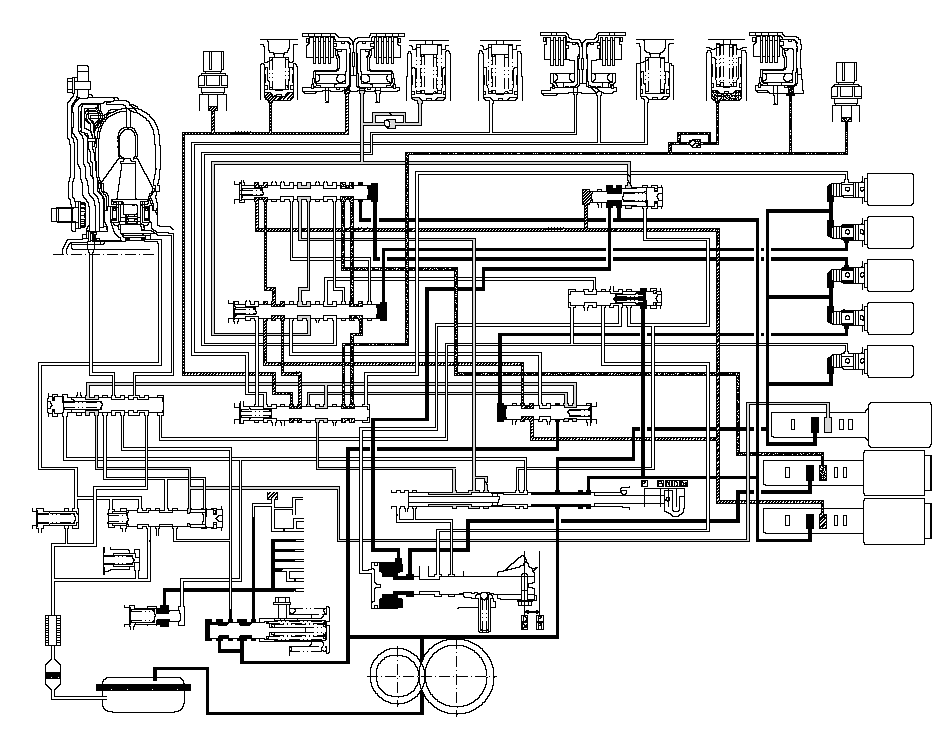
[D] Position: Shifting between 2nd gear and 3rd gear
As the speed of the vehicle reaches the prescribed value, the PCM turns shift solenoid valves C ON, and keeps A and E OFF, and B and D ON. Shift solenoid valve C pressure (SC) is applied to the right side of the shift valve C. The shift valve C is moved to the left side to uncover the ports of A/T clutch pressure control solenoid valves pressures leading to the 2nd and 3rd clutches. The PCM controls the A/T clutch pressure control solenoid valves to regulate hydraulic pressure. A/T clutch pressure control solenoid valve B pressure (56) changes to 2nd clutch pressure (20) at the shift valve A, and A/T clutch pressure control solenoid valve C pressure (57) changes to 3rd clutch pressure (30) at the shift valve A. The 2nd and 3rd clutches are engaged gently.
NOTE: When used, ‘‘left'' or ‘‘right'' indicates direction on the hydraulic circuit.
 TORQUE
CONVERTER3RD CLUTCH
TRANSMISSION FLUID
PRESSURE
SWITCH3RD
ACCUMULATOR3RD
CLUTCH1ST
CLUTCH1ST
ACCUMULATOR4TH
ACCUMULATOR4TH
CLUTCH5TH
CLUTCH5TH
ACCUMULATOR2ND
ACCUMULATOR2ND
CLUTCH2ND CLUTCH
TRANSMISSION FLUID
PRESSURE
SWITCH303095301095104040505020952020919094LOCK-UP
SHIFT
VALVEX55'94917559692SE93XXX5AXX565E575H5C5B5G4SCSHIFT
VALVE
CSHIFT
VALVE
BX5H5B5G3C5E5CSBX5N5L5JX10405FSHIFT
VALVE
AX5N5030X1A1BX55'5FSA10344'X57SERVO CONTROL VALVESHIFT VALVE E3CXSEX3B3'345K5K20XSDX5L5J1A55'57X1XSHIFT
VALVE
DTORQUE
CONVERTER
CHECK
VALVEX939090X939096X925597COOLER
CHECK
VALVEX93ATF
COOLERLOCK-UP
CONTROL
VALVE957XXRELIEF VALVE99AXHXAXHXIDLE
SHAFTIDLE GEARMAINSHAFTCOUNTERSHAFTFINAL DRIVE
GEARSECONDARY
SHAFT929511REGULATOR VALVESERVO VALVEATF PUMP3'4'4''X3B3A3A3AX1B5A5A3714MANUAL VALVESHIFT
SOLENOID
VALVESSAA: OFFB: ONC: OND: ONE: OFFABCXXXXXSBSCSDSE55X1XAX56X4''XAX574XAXXA/T CLUTCH PRESSURE
CONTROL SOLENOID VALVES111
Hydraulic Flow (cont'd)
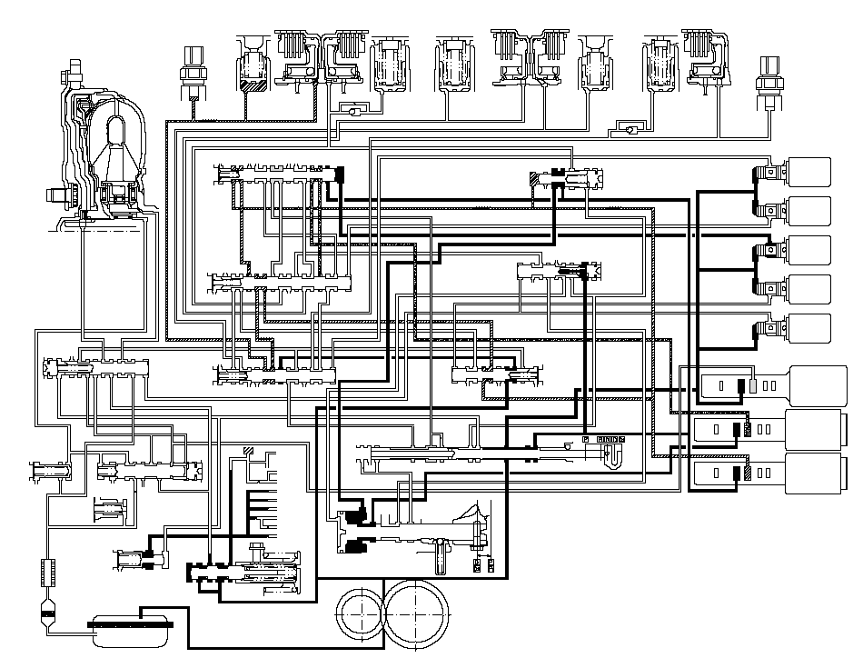
[D] Position: Driving in 3rd gear
The PCM turns shift solenoid valves B, D, A, and E OFF, and C ON. Shift solenoid valve B pressure (SB) in the right side of the shift valve B is released, and the shift valve B is moved to the right side. Shift solenoid valve D pressure (SD) in the left side of the shift valve D is released, and the shift valve D is moved to the left side. These valves movement switches the port of A/T clutch pressure control solenoid valve C pressure leading to the 3rd clutch.
A/T clutch pressure control solenoid valve C pressure (57) changes to (5J) at the shift solenoid valve D and to (5K) at the shift valve B, and becomes 3rd clutch pressure (30) at the shift valve A. The 3rd clutch pressure (30) is applied to the 3rd clutch, and the 3rd clutch is engaged securely.
NOTE: When used, ‘‘left'' or ‘‘right'' indicates direction on the hydraulic circuit.
 TORQUE
CONVERTER3RD CLUTCH
TRANSMISSION FLUID
PRESSURE
SWITCH3RD
ACCUMULATOR3RD
CLUTCH1ST
CLUTCH1ST
ACCUMULATOR4TH
ACCUMULATOR4TH
CLUTCH5TH
CLUTCH5TH
ACCUMULATOR2ND
ACCUMULATOR2ND
CLUTCH2ND CLUTCH
TRANSMISSION FLUID
PRESSURE
SWITCH303095301095104040505020952020919094LOCK-UP
SHIFT
VALVEX55'94917559692SE93XXX5AXX565E575H5C5B5G4SCSHIFT
VALVE
CSHIFT
VALVE
BX5H5B5G3C5E5CSBX5N5L5JX10405FSHIFT
VALVE
AX5N5030X1A1BX55'5FSA10344'X57SERVO CONTROL VALVESHIFT VALVE E3CXSEX3B3'345K5K20XSDX5L5J1A55'57X1XSHIFT
VALVE
DTORQUE
CONVERTER
CHECK
VALVEX939090X939096X925597COOLER
CHECK
VALVEX93ATF
COOLERLOCK-UP
CONTROL
VALVE957XXRELIEF VALVE99AXHXAXHXIDLE
SHAFTIDLE GEARMAINSHAFTCOUNTERSHAFTFINAL DRIVE
GEARSECONDARY
SHAFT929511REGULATOR VALVESERVO VALVEATF PUMP3'4'4''X3B3A3A3AX1B5A5A3714MANUAL VALVESHIFT
SOLENOID
VALVESSAA: OFFB: OFFC: OND: OFFE: OFFABCXXXXXSBSCSDSE55X1XAX56X4''XAX574XAXXA/T CLUTCH PRESSURE
CONTROL SOLENOID VALVES111
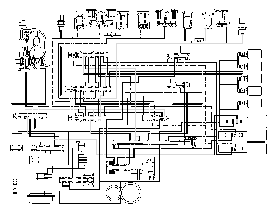
[D] Position: Shifting between 3rd gear and 4th gear
As the speed of the vehicle reaches the prescribed value, the PCM turns shift solenoid valves C OFF, and keeps A, B, D and E OFF. Shift solenoid valve C pressure (SC) in the right side of the shift valve C is released. The shift valve C is moved to the right side to uncover the ports of A/T clutch pressure control solenoid valves B and C pressures leading to the 3rd and 4th clutches. The PCM controls the A/T clutch pressure control solenoid valves to regulate hydraulic pressure. A/T clutch pressure control solenoid valve B pressure changes to 3rd clutch pressure (30) at the shift valve A, and A/T clutch pressure control solenoid valve B pressure (56) changes to 4th clutch pressure (40) at the shift valve B. The 3rd and 4th clutches are engaged gently.
NOTE: When used, ‘‘left'' or ‘‘right'' indicates direction on the hydraulic circuit.
 TORQUE
CONVERTER3RD CLUTCH
TRANSMISSION FLUID
PRESSURE
SWITCH3RD
ACCUMULATOR3RD
CLUTCH1ST
CLUTCH1ST
ACCUMULATOR4TH
ACCUMULATOR4TH
CLUTCH5TH
CLUTCH5TH
ACCUMULATOR2ND
ACCUMULATOR2ND
CLUTCH2ND CLUTCH
TRANSMISSION FLUID
PRESSURE
SWITCH303095301095104040505020952020919094LOCK-UP
SHIFT
VALVEX55'94917559692SE93XXX5AXX565E575H5C5B5G4SCSHIFT
VALVE
CSHIFT
VALVE
BX5H5B5G3C5E5CSBX5N5L5JX10405FSHIFT
VALVE
AX5N5030X1A1BX55'5FSA10344'X57SERVO CONTROL VALVESHIFT VALVE E3CXSEX3B3'345K5K20XSDX5L5J1A55'57X1XSHIFT
VALVE
DTORQUE
CONVERTER
CHECK
VALVEX939090X939096X925597COOLER
CHECK
VALVEX93ATF
COOLERLOCK-UP
CONTROL
VALVE957XXRELIEF VALVE99AXHXAXHXIDLE
SHAFTIDLE GEARMAINSHAFTCOUNTERSHAFTFINAL DRIVE
GEARSECONDARY
SHAFT929511REGULATOR VALVESERVO VALVEATF PUMP3'4'4''X3B3A3A3AX1B5A5A3714MANUAL VALVESHIFT
SOLENOID
VALVESSAA: OFFB: OFFC: OFFD: OFFE: OFFABCXXXXXSBSCSDSE55X1XAX56X4''XAX574XAXXA/T CLUTCH PRESSURE
CONTROL SOLENOID VALVES111
Hydraulic Flow (cont'd)
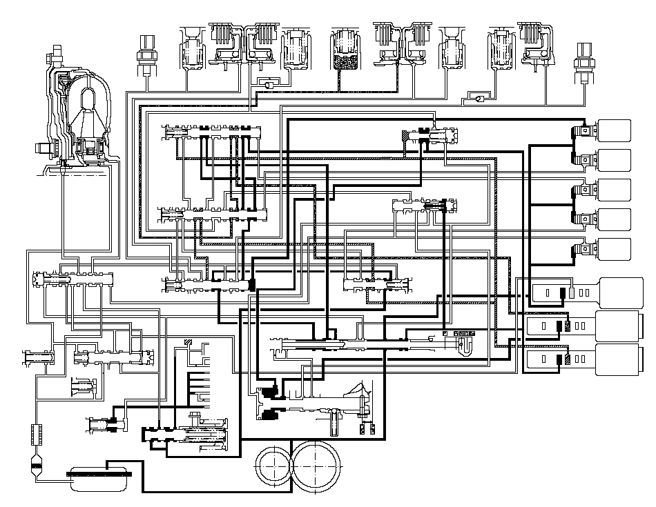
[D] Position: Driving in 4th gear
The PCM turns shift solenoid valves A ON, and keeps B, C, D and E OFF. Shift solenoid valve A pressure (SA) is applied to the right side of the shift valve A. The shift valve A is moved to the left side to cover the ports of A/T clutch pressure control solenoid valves A and C pressure leading to the 2nd and 3rd clutches.
A/T clutch pressure control solenoid valve B pressure (56) changes to (5G) at the shift solenoid valve C, and becomes 4th clutch pressure (40) at the shift valve B. The 4th clutch pressure (40) is regulated to high by the A/T clutch pressure control solenoid valve B, and the 4th clutch is engaged securely.
NOTE: When used, ‘‘left'' or ‘‘right'' indicates direction on the hydraulic circuit.
 TORQUE
CONVERTER3RD CLUTCH
TRANSMISSION FLUID
PRESSURE
SWITCH3RD
ACCUMULATOR3RD
CLUTCH1ST
CLUTCH1ST
ACCUMULATOR4TH
ACCUMULATOR4TH
CLUTCH5TH
CLUTCH5TH
ACCUMULATOR2ND
ACCUMULATOR2ND
CLUTCH2ND CLUTCH
TRANSMISSION FLUID
PRESSURE
SWITCH303095301095104040505020952020919094LOCK-UP
SHIFT
VALVEX55'94917559692SE93XXX5AXX565E575H5C5B5G4SCSHIFT
VALVE
CSHIFT
VALVE
BX5H5B5G3C5E5CSBX5N5L5JX10405FSHIFT
VALVE
AX5N5030X1A1BX55'5FSA10344'X57SERVO CONTROL VALVESHIFT VALVE E3CXSEX3B3'345K5K20XSDX5L5J1A55'57X1XSHIFT
VALVE
DTORQUE
CONVERTER
CHECK
VALVEX939090X939096X925597COOLER
CHECK
VALVEX93ATF
COOLERLOCK-UP
CONTROL
VALVE957XXRELIEF VALVE99AXHXAXHXIDLE
SHAFTIDLE GEARMAINSHAFTCOUNTERSHAFTFINAL DRIVE
GEARSECONDARY
SHAFT929511REGULATOR VALVESERVO VALVEATF PUMP3'4'4''X3B3A3A3AX1B5A5A3714MANUAL VALVESHIFT
SOLENOID
VALVESSAA: ONB: OFFC: OFFD: OFFE: OFFABCXXXXXSBSCSDSE55X1XAX56X4''XAX574XAXXA/T CLUTCH PRESSURE
CONTROL SOLENOID VALVES111
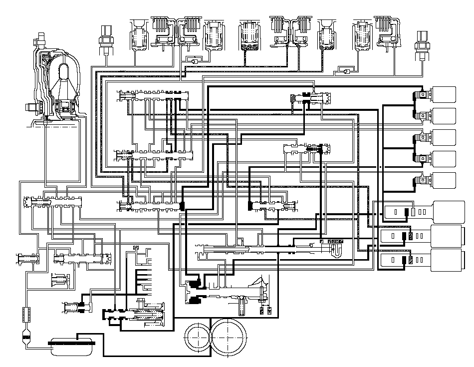
[D] Position: Shifting between 4th gear and 5th gear
As the speed of the vehicle reaches the prescribed value, the PCM turns shift solenoid valves D ON, and keeps A ON, and B, C and E OFF. Shift solenoid valve D pressure (SD) in applied to the left side of the shift valve D. The shift valve D is moved to the right side to uncover the port of A/T clutch pressure control solenoid valve C pressure to the 5th clutch. A/T clutch pressure control solenoid valve B pressure (56) changes to 4th clutch pressure (40) at the shift valve B. A/T clutch pressure control solenoid valve C pressure (57) changes to (5L) at the shift valve D and to (5N) at the shift valve B, and becomes 5th clutch pressure (50) at the shift valve A. The 4th and 5th clutches are engaged gently.
NOTE: When used, ‘‘left'' or ‘‘right'' indicates direction on the hydraulic circuit.
 TORQUE
CONVERTER3RD CLUTCH
TRANSMISSION FLUID
PRESSURE
SWITCH3RD
ACCUMULATOR3RD
CLUTCH1ST
CLUTCH1ST
ACCUMULATOR4TH
ACCUMULATOR4TH
CLUTCH5TH
CLUTCH5TH
ACCUMULATOR2ND
ACCUMULATOR2ND
CLUTCH2ND CLUTCH
TRANSMISSION FLUID
PRESSURE
SWITCH303095301095104040505020952020919094LOCK-UP
SHIFT
VALVEX55'94917559692SE93XXX5AXX565E575H5C5B5G4SCSHIFT
VALVE
CSHIFT
VALVE
BX5H5B5G3C5E5CSBX5N5L5JX10405FSHIFT
VALVE
AX5N5030X1A1BX55'5FSA10344'X57SERVO CONTROL VALVESHIFT VALVE E3CXSEX3B3'345K5K20XSDX5L5J1A55'57X1XSHIFT
VALVE
DTORQUE
CONVERTER
CHECK
VALVEX939090X939096X925597COOLER
CHECK
VALVEX93ATF
COOLERLOCK-UP
CONTROL
VALVE957XXRELIEF VALVE99AXHXAXHXIDLE
SHAFTIDLE GEARMAINSHAFTCOUNTERSHAFTFINAL DRIVE
GEARSECONDARY
SHAFT929511REGULATOR VALVESERVO VALVEATF PUMP3'4'4''X3B3A3A3AX1B5A5A3714MANUAL VALVESHIFT
SOLENOID
VALVESSAA: ONB: OFFC: OFFD: ONE: OFFABCXXXXXSBSCSDSE55X1XAX56X4''XAX574XAXXA/T CLUTCH PRESSURE
CONTROL SOLENOID VALVES111
Hydraulic Flow (cont'd)
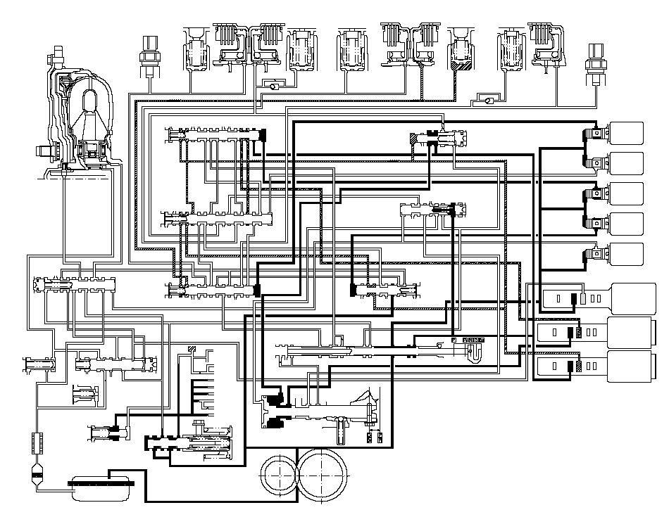
[D] Position: Driving in 5th gear
The PCM turns shift solenoid valves C ON, and keeps A and D ON, and B and E OFF. Shift solenoid valve C pressure (SC) is applied to the right side of the shift valve C. The shift valve C is moved to the left side to switch the port of A/T clutch pressure control solenoid valve B pressure leading to the 4th clutch.
The 5th clutch pressure (50) is regulated to high by the A/T clutch pressure control solenoid valve C, and the 5th clutch is engaged securely.
NOTE: When used, ‘‘left'' or ‘‘right'' indicates direction on the hydraulic circuit.
 TORQUE
CONVERTER3RD CLUTCH
TRANSMISSION FLUID
PRESSURE
SWITCH3RD
ACCUMULATOR3RD
CLUTCH1ST
CLUTCH1ST
ACCUMULATOR4TH
ACCUMULATOR4TH
CLUTCH5TH
CLUTCH5TH
ACCUMULATOR2ND
ACCUMULATOR2ND
CLUTCH2ND CLUTCH
TRANSMISSION FLUID
PRESSURE
SWITCH303095301095104040505020952020919094LOCK-UP
SHIFT
VALVEX55'94917559692SE93XXX5AXX565E575H5C5B5G4SCSHIFT
VALVE
CSHIFT
VALVE
BX5H5B5G3C5E5CSBX5N5L5JX10405FSHIFT
VALVE
AX5N5030X1A1BX55'5FSA10344'X57SERVO CONTROL VALVESHIFT VALVE E3CXSEX3B3'345K5K20XSDX5L5J1A55'57X1XSHIFT
VALVE
DTORQUE
CONVERTER
CHECK
VALVEX939090X939096X925597COOLER
CHECK
VALVEX93ATF
COOLERLOCK-UP
CONTROL
VALVE957XXRELIEF VALVE99AXHXAXHXIDLE
SHAFTIDLE GEARMAINSHAFTCOUNTERSHAFTFINAL DRIVE
GEARSECONDARY
SHAFT929511REGULATOR VALVESERVO VALVEATF PUMP3'4'4''X3B3A3A3AX1B5A5A3714MANUAL VALVESHIFT
SOLENOID
VALVESSAA: ONB: OFFC: OND: ONE: OFFABCXXXXXSBSCSDSE55X1XAX56X4''XAX574XAXXA/T CLUTCH PRESSURE
CONTROL SOLENOID VALVES111
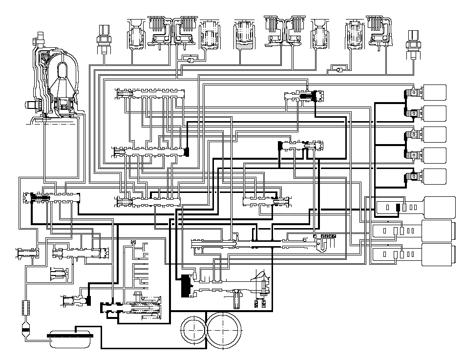
[R] Position: Shifting to [R] position from [P] or [N] position
When shifting in the [R] position, the PCM turns shift solenoid valves B and E ON, and A, C, and D OFF. Shift solenoid valve B pressure (SB) is applied to the right side of the shift valve B, and the shift valve B is moved to left side. Shift solenoid valve E pressure (SE) is applied to the left side of the shift valve E, and the shift valve E is moved to the right side. Line pressure (1) changes to (3) at the manual valve, and flows to the servo valve via the shift valve E. The servo valve is moved to reverse range position. Movement of the shift valves B and E, and servo valve creates 4th clutch pressure line between the 4th clutch and the A/T clutch pressure control solenoid valve A. The 4th clutch pressure (40) is applied to the 4th clutch, and the 4th clutch is engaged gently.
NOTE: When used, ‘‘left'' or ‘‘right'' indicates direction on the hydraulic circuit.
 TORQUE
CONVERTER3RD CLUTCH
TRANSMISSION FLUID
PRESSURE
SWITCH3RD
ACCUMULATOR3RD
CLUTCH1ST
CLUTCH1ST
ACCUMULATOR4TH
ACCUMULATOR4TH
CLUTCH5TH
CLUTCH5TH
ACCUMULATOR2ND
ACCUMULATOR2ND
CLUTCH2ND CLUTCH
TRANSMISSION FLUID
PRESSURE
SWITCH303095301095104040505020952020919094LOCK-UP
SHIFT
VALVEX55'94917559692SE93XXX5AXX565E575H5C5B5G4SCSHIFT
VALVE
CSHIFT
VALVE
BX5H5B5G3C5E5CSBX5N5L5JX10405FSHIFT
VALVE
AX5N5030X1A1BX55'5FSA10344'X57SERVO CONTROL VALVESHIFT VALVE E3CXSEX3B3'345K5K20XSDX5L5J1A55'57X1XSHIFT
VALVE
DTORQUE
CONVERTER
CHECK
VALVEX939090X939096X925597COOLER
CHECK
VALVEX93ATF
COOLERLOCK-UP
CONTROL
VALVE957XXRELIEF VALVE99AXHXAXHXIDLE
SHAFTIDLE GEARMAINSHAFTCOUNTERSHAFTFINAL DRIVE
GEARSECONDARY
SHAFT929511REGULATOR VALVESERVO VALVEATF PUMP3'4'4''X3B3A3A3AX1B5A5A3714MANUAL VALVESHIFT
SOLENOID
VALVESSAA: OFFB: ONC: OFFD: OFFE: ONABCXXXXXSBSCSDSE55X1XAX56X4''XAX574XAXXA/T CLUTCH PRESSURE
CONTROL SOLENOID VALVES111
Hydraulic Flow (cont'd)
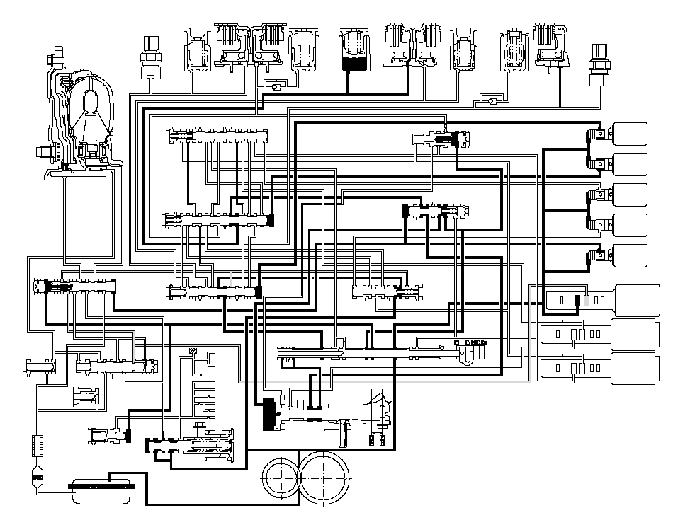
[R] Position: Driving in reverse gear
After starting off in reverse gear, the PCM turns shift solenoid valves A ON, and keeps B and E ON, and C and D OFF. Shift solenoid valve A pressure (SA) is applied to the right side of the shift valve A to cover the port of A/T clutch pressure control solenoid valve A pressure, and to uncover the port of line pressure leading to the 4th clutch creating full line pressure. The 4th clutch is engaged securely with line pressure.Reverse Inhibitor Control
While the vehicle is moving forward, the PCM keeps shift solenoid valve E OFF. The shift valve E covers the port of line pressure (3') leading to the servo valve reverse position. The servo valve cannot be shifted to reverse position, and hydraulic pressure is not applied to the 4th clutch from servo valve for reverse; as a result, power is not transmitted to the reverse direction.
NOTE: When used, ‘‘left'' or ‘‘right'' indicates direction on the hydraulic circuit.
 TORQUE
CONVERTER3RD CLUTCH
TRANSMISSION FLUID
PRESSURE
SWITCH3RD
ACCUMULATOR3RD
CLUTCH1ST
CLUTCH1ST
ACCUMULATOR4TH
ACCUMULATOR4TH
CLUTCH5TH
CLUTCH5TH
ACCUMULATOR2ND
ACCUMULATOR2ND
CLUTCH2ND CLUTCH
TRANSMISSION FLUID
PRESSURE
SWITCH303095301095104040505020952020919094LOCK-UP
SHIFT
VALVEX55'94917559692SE93XXX5AXX565E575H5C5B5G4SCSHIFT
VALVE
CSHIFT
VALVE
BX5H5B5G3C5E5CSBX5N5L5JX10405FSHIFT
VALVE
AX5N5030X1A1BX55'5FSA10344'X57SERVO CONTROL VALVESHIFT VALVE E3CXSEX3B3'345K5K20XSDX5L5J1A55'57X1XSHIFT
VALVE
DTORQUE
CONVERTER
CHECK
VALVEX939090X939096X925597COOLER
CHECK
VALVEX93ATF
COOLERLOCK-UP
CONTROL
VALVE957XXRELIEF VALVE99AXHXAXHXIDLE
SHAFTIDLE GEARMAINSHAFTCOUNTERSHAFTFINAL DRIVE
GEARSECONDARY
SHAFT929511REGULATOR VALVESERVO VALVEATF PUMP3'4'4''X3B3A3A3AX1B5A5A3714MANUAL VALVESHIFT
SOLENOID
VALVESSAA: ONB: ONC: OFFD: OFFE: ONABCXXXXXSBSCSDSE55X1XAX56X4''XAX574XAXXA/T CLUTCH PRESSURE
CONTROL SOLENOID VALVES111
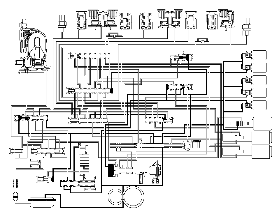
[P] Position
Shift solenoid valves B and E are turned ON, and A, C, and D OFF by the PCM. Line pressure (1) flows to the shift solenoid valves and the A/T clutch pressure control solenoid valve A. Line pressure (3) changes to (3') at the shift valve E, and flows to the servo valve. The servo valve is moved to reverse/park position. Hydraulic pressure is not applied to the clutches.
 TORQUE
CONVERTER3RD CLUTCH
TRANSMISSION FLUID
PRESSURE
SWITCH3RD
ACCUMULATOR3RD
CLUTCH1ST
CLUTCH1ST
ACCUMULATOR4TH
ACCUMULATOR4TH
CLUTCH5TH
CLUTCH5TH
ACCUMULATOR2ND
ACCUMULATOR2ND
CLUTCH2ND CLUTCH
TRANSMISSION FLUID
PRESSURE
SWITCH303095301095104040505020952020919094LOCK-UP
SHIFT
VALVEX55'94917559692SE93XXX5AXX565E575H5C5B5G4SCSHIFT
VALVE
CSHIFT
VALVE
BX5H5B5G3C5E5CSBX5N5L5JX10405FSHIFT
VALVE
AX5N5030X1A1BX55'5FSA10344'X57SERVO CONTROL VALVESHIFT VALVE E3CXSEX3B3'345K5K20XSDX5L5J1A55'57X1XSHIFT
VALVE
DTORQUE
CONVERTER
CHECK
VALVEX939090X939096X925597COOLER
CHECK
VALVEX93ATF
COOLERLOCK-UP
CONTROL
VALVE957XXRELIEF VALVE99AXHXAXHXIDLE
SHAFTIDLE GEARMAINSHAFTCOUNTERSHAFTFINAL DRIVE
GEARSECONDARY
SHAFT929511REGULATOR VALVESERVO VALVEATF PUMP3'4'4''X3B3A3A3AX1B5A5A3714MANUAL VALVESHIFT
SOLENOID
VALVESSAA: OFFB: ONC: OFFD: OFFE: ONABCXXXXXSBSCSDSE55X1XAX56X4''XAX574XAXXA/T CLUTCH PRESSURE
CONTROL SOLENOID VALVES111
Lock-up System
The lock-up mechanism of the torque converter clutch operates in [D] position (2nd, 3rd, 4th and 5th), in [D3] position ( 2nd and 3rd), and [M] (manual mode) position (3rd, 4th and 5th). The pressurized fluid is drained from the back of the torque converter through a fluid passage, causing the torque converter clutch piston to be held against the torque converter cover. As this takes place, the mainshaft rotates at the same speed as the engine crankshaft. Together with the hydraulic control, the PCM optimizes the timing and volume of the lock-up mechanism. When the shift solenoid valve E is turned on by the PCM, shift solenoid valve E pressure switches the lock-up shift valve lock-up on and off. The A/T clutch pressure control solenoid valve A and the lock-up control valve control the amount of the lock-up conditions.
Torque Converter Clutch Lock-up ON (Engaging Torque Converter Clutch)
Fluid in the chamber between the torque converter cover and the torque converter clutch piston is drained off, and fluid entered from the chamber between the pump and stator exerts pressure through the torque converter clutch piston against the torque converter cover. The torque converter clutch piston engages with the torque converter cover; the torque converter clutch lock-up is ON, and the mainshaft rotates at the same speed as the engine.
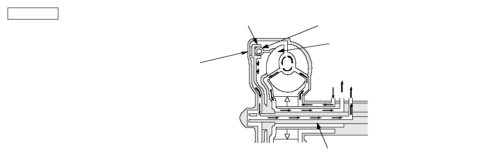 Power flowThe power flows by way of:Engine
¯
Drive plate
¯
Torque converter cover
¯
Torque converter clutch piston
¯
Damper spring
¯
Turbine
¯
MainshaftMAINSHAFTTURBINEDAMPER SPRINGTORQUE CONVERTER
CLUTCH PISTONTORQUE CONVERTER
COVERTo ATF coolerINLETOUTLET
Torque Converter Clutch Lock-up OFF (Disengaging Torque Converter Clutch)
Fluid entering from the chamber between the torque converter cover and the torque converter clutch piston passes through the torque converter and goes out from the chambers between the turbine and the stator, and between the pump and the stator. As a result, the torque converter clutch piston moves away from the torque converter, and the torque converter clutch lock-up is released; torque converter clutch lock-up is OFF.
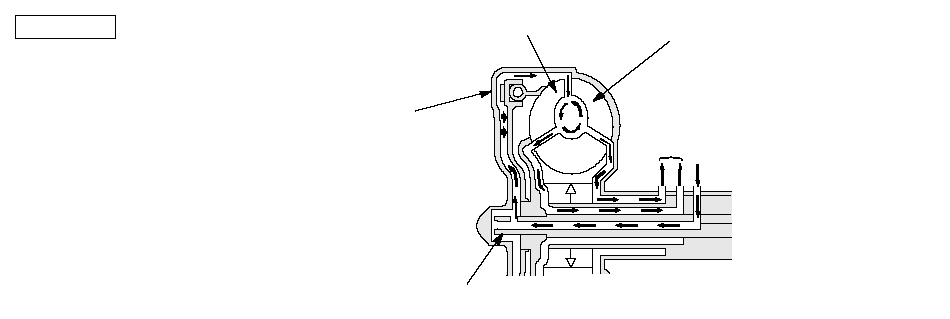 Power flowEngine
¯
Drive plate
¯
Torque converter cover
¯
Pump
¯
Turbine
¯
MainshaftMAINSHAFTTURBINETORQUE CONVERTER
COVERPUMPTo ATF coolerINLET
No Lock-up
Shift solenoid valve E is turned OFF by the PCM, and shift solenoid valve E pressure (SE) is not applied to the lock-up shift valve. The lock-up shift valve stays to the right to uncover the torque converter pressure ports leading to the left side of the torque converter and releasing pressure from the right side of the torque converter. Torque converter pressure (92) changes to (94) at the lock-up shift valve, and enters into the left side of the torque converter to disengage the torque converter clutch. The torque converter clutch piston keeps away from the torque converter cover, the torque converter clutch lock-up is OFF.
NOTE: When used, ‘‘left'' or ‘‘right'' indicates direction on the hydraulic circuit.
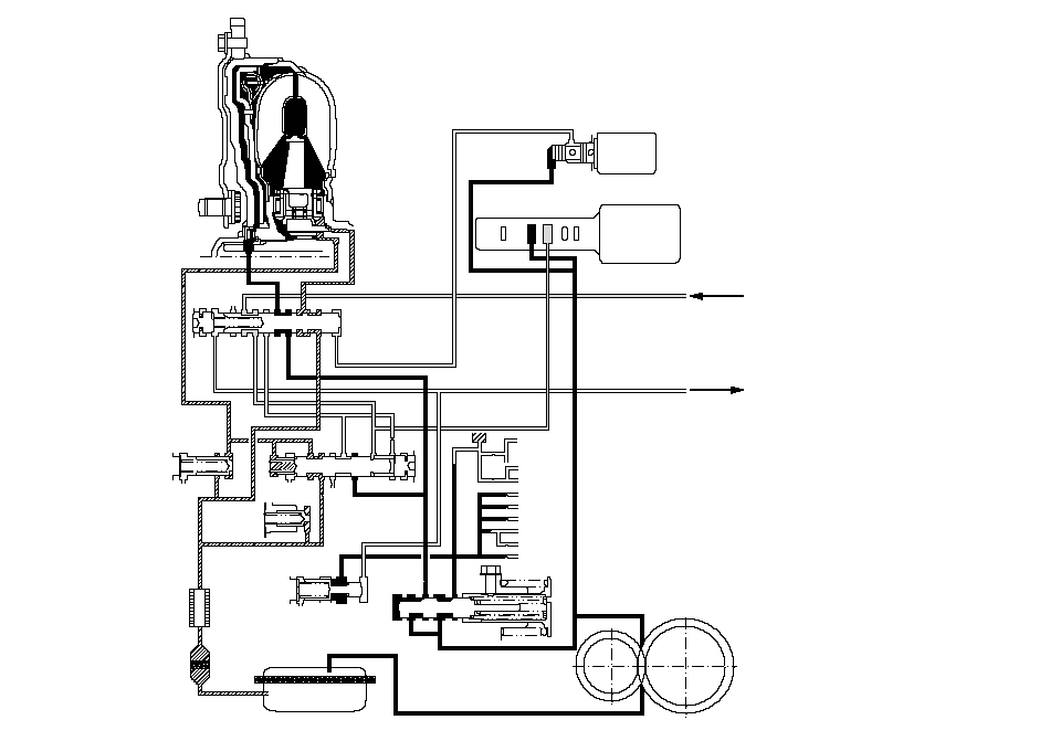 TORQUE
CONVERTERLOCK-UP
SHIFT VALVELOCK-UP
CONTROL
VALVERELIEF VALVEATF
COOLERCOOLER
CHECK
VALVETORQUE
CONVERTER
CHECK VALVEREGULATOR VALVEATF PUMPA/T CLUTCH PRESSURE
CONTROL SOLENOID VALVE AIDLER SHAFTIDLER GEARMAINSHAFTCOUNTERSHAFTFINAL DRIVE
GEARSECONDARY
SHAFT949091X755969293SE919455'9755969090X93X9290X93957XX99929511AXHXAXHXSE1XOFFSHIFT SOLENOID VALVE EX155XAXSHIFT VALVE A and DMANUAL VALVEX93
Lock-up System (cont'd)
Partial Lock-up
As the speed of the vehicle reaches the prescribed value, shift solenoid valve E is turned ON by the PCM, and shift solenoid valve E pressure (SE) is applied to the right side of the lock-up shift valve. The lock-up shift valve is moved to the left side to switch the torque converter pressure (91) port which goes to the right side of the torque converter, and the port of torque converter pressure (94) releasing from the left side of the torque converter. Torque converter pressure (91) flows to the right side of the torque converter to engage the torque converter clutch. The PCM also controls the A/T clutch pressure control solenoid valve A to regulate A/T clutch pressure control solenoid valve A pressure (55) applies to the lock-up shift valve and lock-up control valve. The position of the lock-up control valve depends on A/T clutch pressure control solenoid valve A pressure (55) and torque converter pressure released from the torque converter. The lock-up control valve controls the amount of the torque converter clutch lock-up until fluid between the clutch piston and torque converter cover is released fully; the torque converter clutch is in partial lock-up condition.
NOTE: When used, ‘‘left'' or ‘‘right'' indicates direction on the hydraulic circuit.
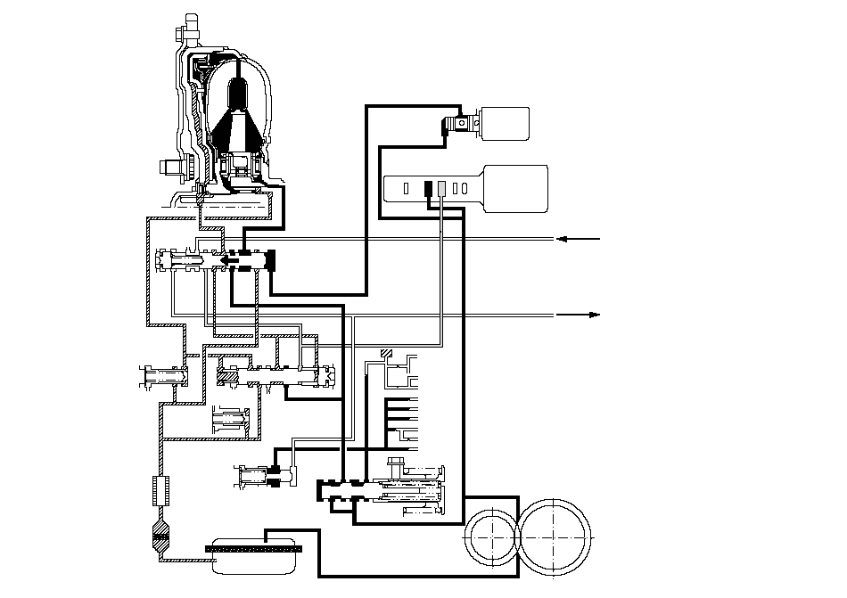 ONTORQUE
CONVERTERLOCK-UP
SHIFT VALVELOCK-UP
CONTROL
VALVERELIEF VALVEATF
COOLERCOOLER
CHECK
VALVETORQUE
CONVERTER
CHECK VALVEREGULATOR VALVEATF PUMPA/T CLUTCH PRESSURE
CONTROL SOLENOID VALVE AIDLER SHAFTIDLER GEARMAINSHAFTCOUNTERSHAFTFINAL DRIVE
GEARSECONDARY
SHAFT949091X755969293SE919455'9755969090X93X9290X93957XX99929511AXHXAXHXSE1XSHIFT SOLENOID VALVE EX155XAXSHIFT VALVE A and DMANUAL VALVEX93
Full Lock-up
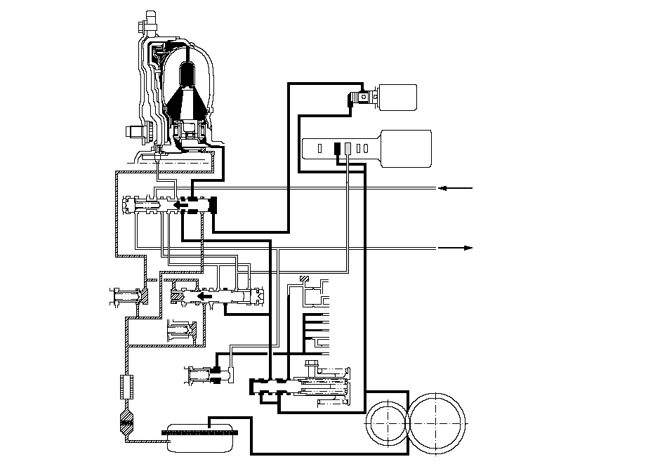
When the vehicle speed increases, the PCM sends a signal to A/T clutch pressure control solenoid valve A to increase A/T clutch pressure control solenoid valve A pressure (55), and the lock-up control valve is moved to the left by the increased pressure. Then torque increased converter pressure (94) from the left side of the torque converter is completely released at the lock-up control valve, and torque converter pressure (91) engages the torque converter clutch securely; the torque converter clutch is in full lock-up condition.
NOTE: When used, ‘‘left'' or ‘‘right'' indicates direction on the hydraulic circuit.
 ONTORQUE
CONVERTERLOCK-UP
SHIFT VALVELOCK-UP
CONTROL
VALVERELIEF VALVEATF
COOLERCOOLER
CHECK
VALVETORQUE
CONVERTER
CHECK VALVEREGULATOR VALVEATF PUMPA/T CLUTCH PRESSURE
CONTROL SOLENOID VALVE AIDLER SHAFTIDLER GEARMAINSHAFTCOUNTERSHAFTFINAL DRIVE
GEARSECONDARY
SHAFT949091X755969293SE919455'9755969090X93X9290X93957XX99929511AXHXAXHXSE1XSHIFT SOLENOID VALVE EX155XAXSHIFT VALVE A and DMANUAL VALVEX93
Shift Lever Mechanism
The shift lever has five positions; the [P], [R], [N], [D], and [D3] positions. The [D] position has two modes; automatic shift mode and manual shift mode with the shift lever moved to the [M] position. The shift lever shifts out of the [P] position and into the [R] position with pressing the shift lever button. The shift lever is engaged with the shift lever link in the [P], [R], [N], [D], and [D3] positions. This unit shifts the transmission using the shift cable connected between the shift cable link and the transmission control shaft.
In the [M] position, the shift lever is disengaged from the shift cable link, and the shift lever can be used to shift gears manually between 1st through 5th, much like a manual transmission.
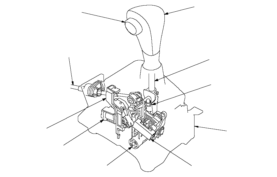 SHIFT LEVERDETENT PLUNGERSHIFT CABLE LINKSHIFT LOCK SOLENOIDSHIFT LOCK RELEASESHIFT LEVER
BRACKET BASESHIFT LEVER KNOBSHIFT LEVER BUTTONTRANSMISSION
GEAR SELECTION SWITCHSHIFT CABLE
Shift Lever Mechanism in [M] Position
When the shift lever shifts to the [M] position, the shift lever is disengaged from the shift cable link, and the shift cable link lock pops up to engage with the shift lever bracket base; the shift cable link and shifting position in the transmission are held in the [D] position.
The shift cable link lock is spring load, it pops up in the [M] position, and does not engage the shift lever in any position except [M].
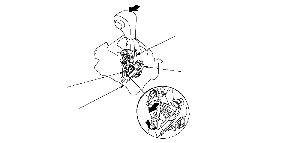 SHIFT LEVERSHIFT CABLE LINKSHIFT LEVER BRACKET BASESHIFT CABLE LINK LOCK
The shift lever fits into the [M] position by using a detent plunger with a spring. When shifting to upshift and downshift positions, the detent plunger is depressed by the detent bracket inner wall, and detent plunger spring puts the shift lever back into the neutral position.
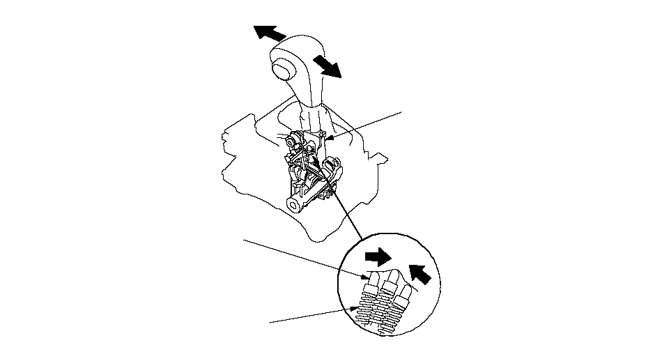 SHIFT LEVERDETENT PLUNGER SPRINGDETENT PLUNGERDOWNSHIFT POSITIONUPSHIFT POSITION
Circuit Diagram-PCM A/T Control System
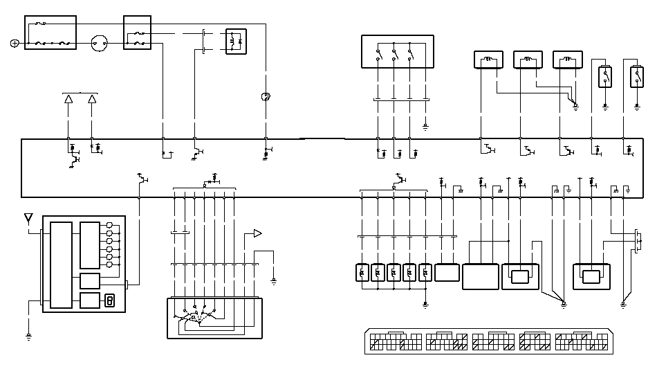 3RD CLUTCH2ND CLUTCHSWITCH FLUID PRESSURETRANSMISSIONSPEED SENSORMAINSHAFTPRESSURE SENSORMANIFOLD ABSOLUTETEMPERATURESENSORATFA/T CLUTCH PRESSUREVALVE CCONTROL SOLENOIDCONTROL SOLENOIDVALVE BA/T CLUTCH PRESSUREA/T CLUTCH PRESSURETRANSMISSIONFLUID PRESSURESWITCH COUNTERSHAFTSPEED SENSORVALVE ACONTROL SOLENOID(19)(15)(8)932(20)(19)(16)(12)(11)10(29)28(26)(25)(10)(14)(17)1211(11)2053118141330(27)2021158(12)18188165213A (31P)B (24P)C (22P)E (31P)PCM Connector Terminal Locations262297431618292423121091514412672117151365432823243021201915(12)10123456793172516510D (17P)19BLKBLKBLKPG1BRN/YELYEL/BLUBRN/YELBLKPG2A4A9LG1G101123GRN/YELA23SG2To 5VS-DND9S-UPD3D2S-MODEG501BRNWHTBLKORN2873BLU/YELBLKGRN/WHTYELS-DNS-UPS-MODETRANSMISSION GEAR SELECTION SWITCHG101YEL/REDWHT/REDGRN/REDGRN/WHTSH DC5GRN/RED8YELDBLKSHIFT SOLENOID VALVESA20VCC2NCA18BLK/BLUA24SG1A30BRN/YELC19NMVCC1A21LG2A8BRN/YELA3ECBAORNBLUGRNREDWHTWHT7C14C3SH ERED/YELYEL36C2SH CGRN125C10BLU/WHTOP3SWBLU/RED12C7BLU/YELLS C+21BRN/WHTC15LS B+123321LS A+C1RED/BLK12G101SH ASH BC6C4POWERTRAIN CONTROL MODULE (PCM) BLU/BLKGRN/WHTC13OP2SWMAPATFTSHIFTDIMMINGCIRCUITCANCELBOXUNDER-DASHFUSE/RELAYSOLENOIDSHIFT LOCKFUSE/RELAY BOXSWITCHBRAKERELAYCUTSTARTERPOSITIONPEDALUNDER-DASHB2POSITIONDRIVERINDICATIONDRIVERCIRCUITAT INDCONTROLLERCANBLU/WHTBLKREDNo.13 (20A)DATA LINK CONNECTORK-LINEE23LT BLUBRNE29SCSLT GRNMET INHD10A5D3WHT/GRNBLU/BLKUNDER-HOOD FUSE/RELAY BOXNo.21 (7.5A)YEL21FWDBLU/YEL76C18FWDATPBLU/YELTo 5VTo 12VGRNE2SLS312578910D3MRVSBK SWE22REDWHT/BLKRED/WHTC12RVSATP6WHT/REDBATPRNATPATPD5C17C9ATPDGRNYEL/GRNREDBLUPNKRED/BLKWHTBLK/BLUBLU/WHTBLKG101BLKD3RYELNo.21 (7.5A)G501BLKNo.19 (15A)ATPPBLUD6A21IGNITION SWITCHGAUGE CONTROL MODULEIG12839415DPRNTRANSMISSION RANGE SWITCHDSTEBLK/REDC20NATPBATTERYPOWERTRAIN CONTROL MODULE (PCM)No.22 (100A)E9BLK/YELIG1No.23 (50A)