Navigation System Diagnosis Test
Navigation System Diagnosis Test
Start-up procedure and Diagnosis Menu
| 1. | Turn the ignition switch ON (II), press ‘‘OK'' on the disclaimer screen, then press and hold the keys in this order: (1) MENU Key. (2) MAP/GUIDE Key, (3) CANCEL Key, and keep them pressed simultaneously for 5 seconds. |
| 2. | After the display changes to the diagnosis menu screen, touch the item you want to check, and the check will start. To return to the previous screen, touch the ‘‘RETURN'' switch on the diagnosis screen.
 Diagnosis Menu ReturnSystem Links Monitor CheckUnit CheckVehicle PositionYaw RateTire-CalibrateIn-line DiagCyclic DiagStart demo mode Diagnosis Menu ReturnSystem Links Monitor CheckUnit CheckVehicle PositionYaw RateTire-CalibrateIn-line DiagCyclic DiagStart demo mode |
System links
- During diagnosis, all of the communication lines connecting the components are shown in yellow.
- If the system is OK, all of the communication lines connecting the components will change to green, the screen will indicate ‘‘OK'', and a tone will sound.
- If there is a problem in the system, the faulty communication line will change to red, the screen will indicate ‘‘NG'', and a tone will sound.
- The indication on the screen will not change until the ignition switch is cycled. After repairing the system, turn the ignition switch OFF to reset the system, then return to the diagnosis menu screen, and run system links again.
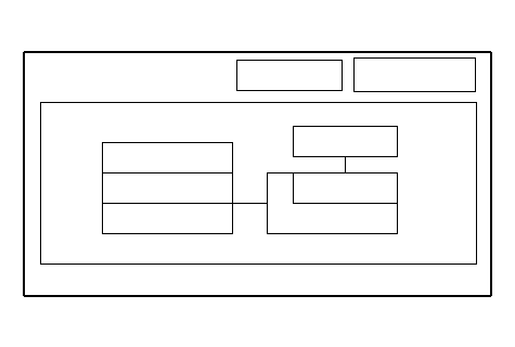 ReturnSystem Links AirconNavi ECUDispAudioANTGPSOK
Tire Calibrate
- The ‘‘AUTO TUNING'' is factory-set to ‘‘ON'', and it should remain on. If you find it has been turned OFF, turn it back ON.
- The ‘‘TIRE-CAL TUNING'' should not be used. The AUTO TUNING function keeps the system in better tune.
 ReturnTire-CalibrateTire-Cal FactorAuto-TuningTire-Cal TuningSTDSet+-ON-x.x%-x.x%
Yaw Rate
‘‘Offset'' is a reference voltage or standard within the yaw rate sensor. It should indicate 1.500 to 3.500 V with the vehicle stopped.
‘‘Sensor'' indicates the voltage output from the yaw rate sensor. It should indicate 1.500 to 3.500 V with the vehicle stopped.
A ‘‘Sensor'' output voltage HIGHER than that of the ''Offset'' voltage indicates the vehicle is turning to the RIGHT.
A ‘‘Sensor'' output voltage LOWER than that of the ''Offset'' voltage indicates the vehicle is turning to the LEFT.
With the vehicle stopped, sitting still, with the engine idling both the ''Offset'' and ''Sensor'' voltages should be within 0.01 V ± of each other.
If not replace the Navigation unit.
Example:
NOTE: The vehicle is stopped, sitting still, with the engine idling.
| Good | ||
|---|---|---|
| Offset | 2.517 V | |
| Sensor | 2.517 V (0.010 V ±) | |
| Bad | ||
|---|---|---|
| Offset | 2.517 V | |
| Sensor | 2.823 V | |
NOTE: Do not try to tune the yaw rate sensor unless instructed by Honda Motor Europe.
 ReturnYaw RateOffsetSensor-x.x%CCW Cal FactorCW Cal Factor-x.x%x.xxxVx.xxxVMonitorTuning
Monitor Check
Touch the item you want to check, and the check starts.
 ReturnRGB ColorMonitor CheckGray TonesColor ChangeTest PatternScreen AdjustmentWhite RasterBlack RasterTouch Test
RGB COLOR
The three primary colors of red, green and blue must be shown.
If any color(s) are missing, troubleshoot for the missing color.
 ReturnGreenRedBlue
WHITE RASTER
The entire display must be shown in white.
 Return
Touch Test
Each switch must be shown on the display and each switch must reverse and sound, when touched.
NOTE: The test may be affected if done in direct sunlight.
 R
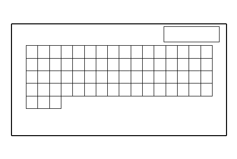
RTest Pattern
All 32 colors including black must be indicated (including the back ground color).
 Return
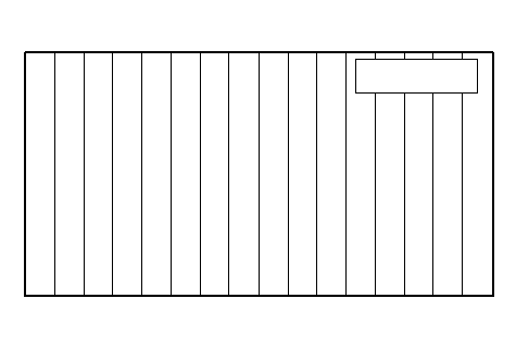
Gray Tone
The gray color should change
 Return
Black Raster
The entire display must be shown in black.
 Return
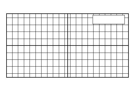
Screen Adjustment
Chage the indicating position using the joystick.
Touch the return to set the changing data.
 ReturnX= 0Y= 0
Unit Check
Touch the item you want to check, and the check starts.
NOTE: Do not use ‘‘Backup Clear'' and ‘‘Force Download''. These commands are for the manufacturer's use only.
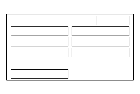 ReturnDispUnit CheckNavi ECUSystem HistoryBackup ClearGPSCar StatusForce Download
Display
When the connection is NG.
First check for loose terminals at the navigation unit and the display unit connectors.
Next check for an open or short in the communication line between the navigation unit and the display unit. If the line is OK, replace the display unit. If the line is found to have an open or short, replace the affected shielded harness.
 ReturnConnectionDispOK
Navi ECU
When any item is NG, replace the navigation unit.
 ReturnNavi ECUOKHigh TmpLow TmpFlash IPLFlash ApplicationRAMVRAM OverlayVRAM BaseModelxx°Cxx°COK[xxxx]OK[xxxx]OKOKxxOK
GPS Information
This screen shows the condition of the GPS reception and the vehicle position.
The vehicle should be parked out side away from building, tall trees, high tension lines for 10 minutes with motor running.
The number of satellites box should contain at least three yellow sateilite icons. If not, troubleshoot for satellite mark not indicated.
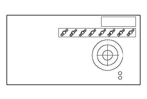 GPS InformationReturnIn UseSearchCurrent PositionLatitude xx°xx¢xx²Longitude xx°xx¢xx²Elevation xxx ft'xx.xx.xx xx:xx xxNumber of
SatellitesWSEN
Car Status
Use the car status screen to check each signal.
If the indication does not match the actual vehicle status, check the applicable signal line.
- VSP (vehicle speed pulse indication)
- OFF when vehicle is not moving
- ON when vehicle is moving
- OFF when vehicle is not moving
- BACK (reverse indication)
- OFF when shift lever is in any position other than reverse
- ON when shift lever is in reverse
- OFF when shift lever is in any position other than reverse
- ILL (illumination indication)
- OFF when parking lights or headlights are off
- ON when parking lights or headlights are on
- OFF when parking lights or headlights are off
 Car Status ReturnVSPBACKILLOFFOFFOFF
Cyclic Diag
This test is for manufacturer's use only. In this test, the system checks the following items repeatedly:
- Navi ECU unit check
- RGB color
- Test pattern
- White raster
- Black raster
To exit this test, press the cancel key.
Vehicle Position
When moving the vehicle with the engine stopped such as ferry or tow truck and vehicle positioning error occured, you can adjust the vehicle position using the joystick.
Start demo mode
This test is for manufacturer's use only. If the indication of this item is changed to ‘‘Stop demo mode'', select this item once and make sure the indication changes to ‘‘Start demo mode''
In-line Diag
This test is for manufacturer's use only. In this test, the system checks the following items:
- System Links
- Car status
- Yaw Rate