Intake Manifold Removal and Installation
Intake Manifold Removal and Installation
Exploded View:
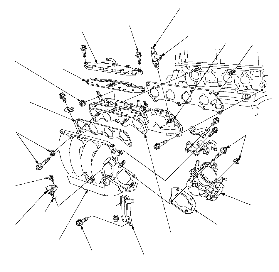 JOINTMARKGASKET
Replace.8 x 1.25 mm
22 N·m (2.2 kgf·m,
16 lbf·ft)THROTTLE
BODYGASKET
Replace.INJECTOR BASE
Replace if cracked or if
mating surface is
damaged.INTAKE MANIFOLD
BRACKETINTAKE MANIFOLD
Replace if cracked or if
mating surface is
damaged.8 x 1.25 mm
22 N·m (2.2 kgf·m,
16 lbf·ft)O-RING
Replace.MANIFOLD ABSOLUTE
PRESSURE (MAP)
SENSOR5 x 0.8 mm
3.4 N·m
(0.35 kgf·m,
2.5 lbf·ft)8 x 1.25 mm
22 N·m (2.2 kgf·m,
16 lbf·ft)GASKET
Replace.8 x 1.25 mm
22 N·m (2.2 kgf·m,
16 lbf·ft)GASKET
Replace.6 x 1.0 mm
12 N·m (1.2 kgf·m,
8.7 lbf·ft)EXHAUST GAS
RECIRCULATION
(EGR) PLATEINTAKE AIR BYPASS (IAB)
THERMAL VALVE
Tighten the valve to 15 N·m
(1.5 kgf·m, 11 lbf·ft), then turn the
valve joint toward the mark.
Removal:
| 1. | Disconnect the intake air temperature (IAT) sensor connector (A).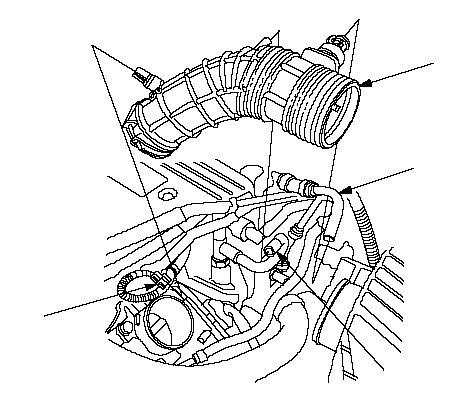 BCDA BCDA |
| 2. | Remove the vacuum hose (B) and breather pipe (C), then remove the intake air duct (D). |
| 3. | Remove the intake manifold cover.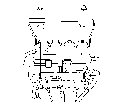 |
| 4. | Remove the throttle cable (A) and cruise control cable (B) by loosening the locknuts (C), then slipping the cable ends out of the accelerator linkage. Take care not to bend the cables when removing them. Always replace any kinked cable with a new one (K20A6 engine).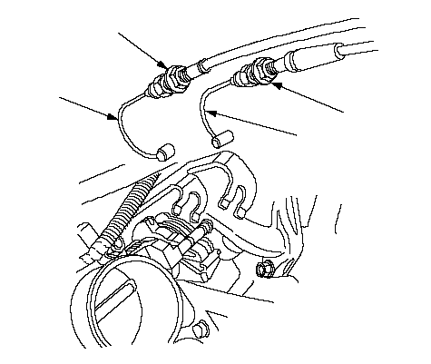 CBCA CBCA |
| 5. | Remove the evaporative emission (EVAP) canister hose (A) and brake booster vacuum hose (B).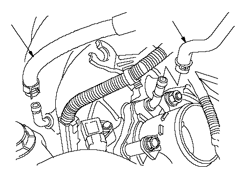 AB AB |
| 6. | Remove the engine wire harness connectors and wire harness clamps from the intake manifold.
|
| 7. | Remove the harness holder (A), harness bracket (B), and remove the harness clamp (C).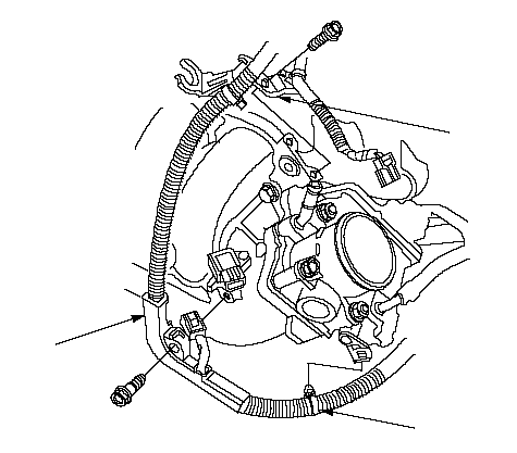 CBA CBA |
| 8. | Remove and plug the water bypass hoses.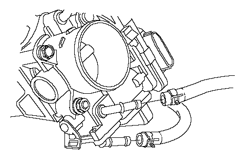 |
| 9. | Remove the harness clamp (A), and the harness connector (B) from the intake manifold bracket, then remove the intake manifold bracket (C).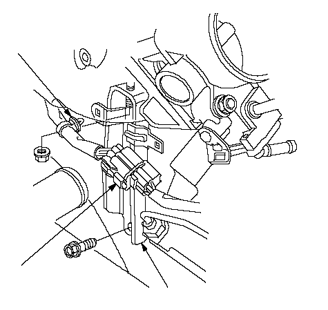 ABC ABC |
| 10. | Remove the vacuum hose.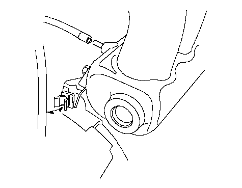 |
| 11. | Remove the intake manifold.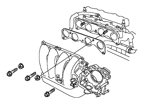 |
Installation:
| 1. | Install the intake manifold (A) with a new gasket (B), and tighten the bolts/nuts in a crisscross pattern in two or three steps, beginning with the inner bolt.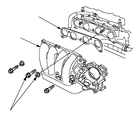 BA8 x 1.25 mm BA8 x 1.25 mm22 N·m (2.2 kgf·m, 16 lbf·ft) |
| 2. | Install the vacuum hose.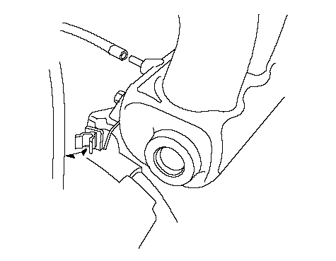 |
| 3. | Install the intake manifold bracket (A), then install the harness clamp (B), and harness connector (C) to the intake manifold bracket.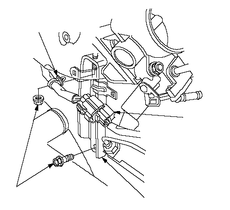 8 x 1.25 mm 8 x 1.25 mm22 N·m (2.2 kgf·m, 16 lbf·ft)BCA |
| 4. | Install the water bypass hoses.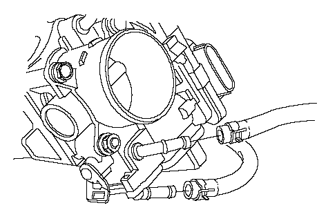 |
| 5. | Install the harness holder (A), harness bracket (B), and install the harness clamp (C).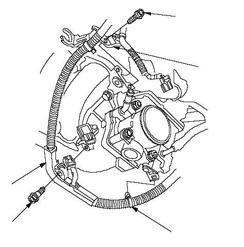 6 x 1.0 mm 6 x 1.0 mm12 N·m (1.2 kgf·m, 8.7 lbf·ft)6 x 1.0 mm 12 N·m (1.2 kgf·m, 8.7 lbf·ft)ACB |
| 6. | Install the evaporative emission (EVAP) canister hose (A) and brake booster vacuum hose (B).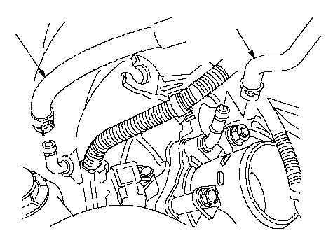 AB AB |
| 7. | Install the throttle cable, then adjust the cable (K20A6 engine). |
| 8. | Install the cruise control cable, then adjust the cable (K20A6 engine). |
| 9. | Install the intake manifold cover.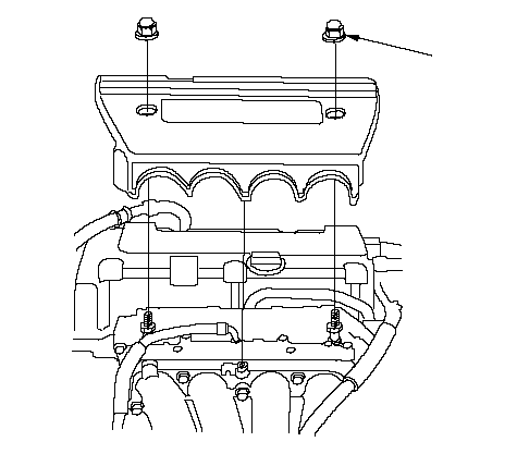 6 x 1.0 mm 6 x 1.0 mm12 N·m (1.2 kgf·m, 8.7 lbf·ft) |
| 10. | Install the intake air duct (A), then connect the intake air temperature (IAT) sensor connector (B), and install the vacuum hose (C) and breather pipe (D).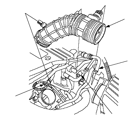 ADCB ADCB |
| 11. | Clean up any spilled engine coolant. |
| 12. | After installation, check that all tubes, hoses and connectors are installed correctly. |
| 13. | Refill the radiator with engine coolant, and bleed air from the cooling system with the heater valve open. |