M/T Assembly Installation

Special Tools Required

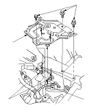
Engine support hanger
 AAR-T1256-J00

Subhanger stay
 07MAK-PY30100

Subframe alignment pin
 070AG-SJAA10S
K24Z3 Engine Model
NOTE: Use fender covers to avoid damaging painted surfaces.
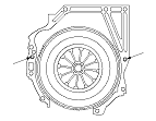
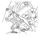
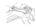
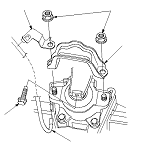
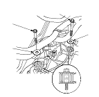
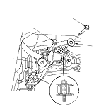
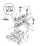
  1. Make sure two dowel pins (A) are installed prescribed hole on the engine block as shown.
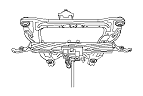
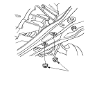
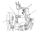
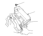
  1. Place the transmission on the transmission jack, and raise it to the engine unit level.
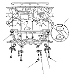
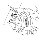
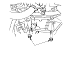
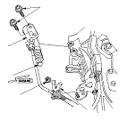
  1. Join the transmission and engine unit with putting through the transmission mainshaft to the clutch pressure plate and the clutch disc until it becomes no gap between the transmission housing and the engine block.

  1. Install the lower transmission mounting bolts (A).
Front side
Rear side

  1. Install the clutch case cover (A).

  1. Install the lower transmission mount (A) with new bolts.

  1. Install the rear engine mount bracket (A) with new bolts.

  1. Support the front suspension subframe with a piece of wood and a jack.

  1. Position the steering gearbox washers (A) on the front suspension subframe (B), and lift up the subframe. Do not contact with the subframe and body frame in this procedure.
  1. Loosely install new four front subframe mounting bolts with each stiffener, the new rear stiffener mounting bolts (C), and the front stiffener mounting bolts (D).

  1. Align the front suspension subframe using the subframe alignment pin (A). Vertically install the subframe alignment pin, and align the right-rear corner of the subframe and vehicle frame holes, then loosely tighten the subframe mounting bolt (B) until the front suspension subframe contacts the body frame.
  1. Loosely tighten the left-rear subframe mounting bolt using the same procedure as the right-rear with the subframe alignment pin.
  1. Partially tighten the right and left front subframe mounting bolts.
  1. Tighten the right-rear subframe mounting bolt to the specified torque with the subframe alignment pin in the positioning hole.
  1. Tighten the left-rear subframe mounting bolt to the specified torque with the subframe alignment pin in the positioning hole.

  1. Tighten the right and left front subframe mounting bolts (A) to the specified torque.
  1. Tighten the rear and front stiffener mounting bolts to the specified torque.
  1. Check all of the front subframe mounting bolts, and retighten if necessary.
  1. Remove the jack and wood piece.

  1. Install the nuts (A) securing lower transmission mount.

  1. Install both sides of the front subframe mid mount (A) with new bolts.
  1. Install the ground cable (B) to the transmission housing.
  1. Clean the mating surfaces of the brake disc and the inside of the wheel, then install the front wheels.
  1. Lower the vehicle on a lift.

  1. Install the upper transmission mounting bolts (A).

  1. Install the transmission hanger C to the transmission housing.

  1. Loosely install the transmission mount bracket (A) to the transmission housing with new bolts.

  1. Install the new rear engine mount bracket upper mounting bolt (A).
  1. Loosely install the new rear engine mount bolts (B).

  1. Connect the vacuum hose (A).
  1. Loosely install the new front engine mount bolt (B).
    NOTE: Install the engine mount stop (C) and the vacuum hose bracket (D) after tightening the front engine mount bolt to the specified torque.
  1. Remove the engine support hanger and the subhanger stay.
  1. Tighten the rear engine mount bolts to the specified torque value.
  1. Tighten the transmission mount bolts to the specified torque value.
  1. Tighten the front engine mount bolt to the specified torque value, then install the vacuum hose bracket and the engine mount stop with new nuts.

  1. Install the harness holder (A) to the bracket (B).

  1. Set back the hung up steering gearbox to regular position, then loosely install the all four steering gearbox mounting bolts with top washers (A).
  1. Tighten the front/driver's side of the steering gearbox mounting bolt (B) to the specified torque value.
  1. Tighten the front/passenger's side of the steering gearbox mounting bolt (C) to the specified torque value.
  1. Tighten the rear side of two steering gearbox mounting bolts (D) to the specified torque value.
Driver's side
Passenger's side

  1. Install the bracket (A), then install the harness clamp (B) and the hose (C) to the bracket.

  1. Connect the back-up light switch connector (A) and the reverse lockout solenoid connector (B), then install the harness clamp (C).
  1. Connect the output shaft (countershaft) speed sensor connector (D), and install the harness clamp (E).

  1. Apply a light coat of silicone grease to the cable ends (A), and connect the cable end to the change lever assembly (B), then install the shift cable bracket (C) and the lock pins (D). Do not bend or damage the shift cable.
    NOTE: When you apply the silicone grease, make sure not to adhere to the terminal part of connectors and surrounding switches. Also do not touch the switches and the terminal part of connector by hands or glove that adheres the silicone grease.

  1. Install the under-hood fuse/relay box (A).

  1. Apply a light coat of molybdenum grease to the end of slave cylinder rod (A).
  1. Install the clutch hose bracket (B), then install the slave cylinder (C). Do not bend or damage the clutch line.

  1. Install the battery base (A) and the ground cable clamp (B).
  1. Check the shift lever and the clutch operation.
  1. Test-drive the vehicle.