|
DTC 76-3x (‘‘x'' can be 0 thru 9 or A thru F):
Faulty F-CAN communication or Internal Failure of E-pretensioner Unit (K24Z3 engine)
-
-
Turn the ignition switch to LOCK (0), and wait for 10 seconds.
-
Turn the ignition switch to ON (II), and wait for 10 seconds.
-
-
Turn the ignition switch to LOCK (0).
-
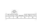
Turn the ignition switch to ON (II), and check that the ACC indicator comes on and then goes off.
|
Does the ACC indicator go off?
|
-
Turn the ignition switch to LOCK (0).
-
Turn the ignition switch to ON (II), and check that the VSA indicator comes on and then goes off.
|
Does the VSA indicator go off?
|
-
Turn the ignition switch to LOCK (0).
-
Turn the ignition switch to ON (II), and check that the ECM/PCM indicator comes on and then goes off.
|
Does the ECM/PCM indicator go off?
|
-
Turn the ignition switch to LOCK (0).
-
-
-
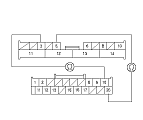
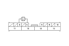
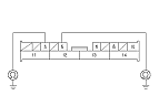
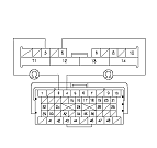
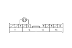
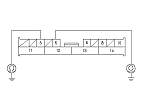
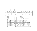
Check continuity between No. 3 terminal of E-pretensioner unit 14P connector and the No. 10 terminal of ACC unit connector (20P), and between the No. 5 terminal of the left engine compartment subharness 14P connector (LHD models) or E-pretensioner unit 14P connector (RHD models) and the No. 20 terminal of ACC unit connector (20P).
|
YES
|
-
|
|
|
NO
|
-
|
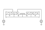
Open between the left engine compartment subharness 14P connector (LHD models) or E-pretensioner subharness 14P connector (RHD models) and ACC unit connector (20P).■
|
|