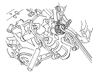
Engine Oil Pump Overhaul
|
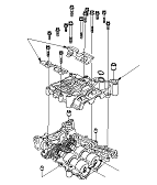
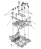
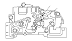
Exploded View
Special Tools Required
Pin driver, 6.0 mm
07744-0010500
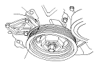
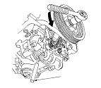
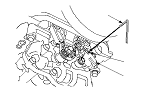
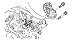
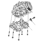
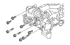
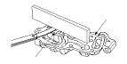
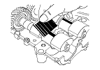
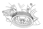
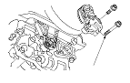
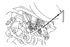
Oil Pump Removal
|
|
|
|
|
|
|
|
|
|
|
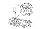
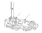
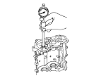
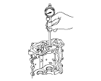
Oil Pump Inspection
|
|
|
|
|||||||
|
|
|||||||
|
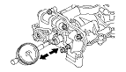
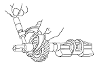
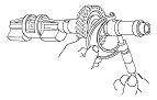
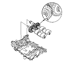
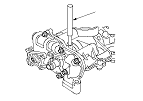
Balancer Shaft Inspection
|
|
|||||||
|

|
|
|
|
Front
Rear
|
||||||||||||||
|
Front
Rear
|
||||||||||||||||||||
|
|
||||||
|
|
|
|
|
|
|
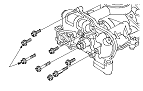
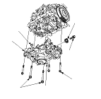
Oil Pump Installation
|
|
|
|
|
|
|
|
|
|
|
|