-
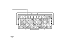
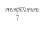
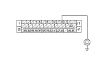
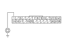
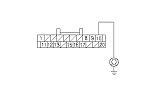
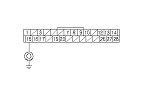
Check for continuity between ECM/PCM connector terminal A4 and body ground.
|
YES
|
-
|
Repair short in the wire between the ECM/PCM terminals A4 and the gauge control module, the VSA modulator-control unit, the yaw rate-lateral acceleration sensor, the EPS control unit, the SRS unit, the LKAS control unit (with driving support system), the ACC unit (with driving support system), the E-pritensioner unit (with driving support system), the navigation unit (with navigation system), or the DLC.■
|
|
NO
|
-
|
|
-
Reconnect all connectors.
-
-
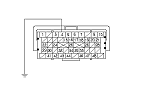
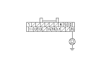
Disconnect the gauge control module 32P connector.
-
Turn the ignition switch to ON (II), and read the HDS.
|
Does the HDS identify the vehicle?
|
-
Turn the ignition switch to LOCK (0).
-
Reconnect the gauge control module 32P connector.
-
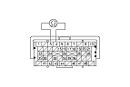
Disconnect the VSA modulator-control unit 47P connector.
-
Turn the ignition switch to ON (II), and read the HDS.
|
Does the HDS identify the vehicle?
|
-
Turn the ignition switch to LOCK (0).
-
Reconnect the VSA modulator-control unit 47P connector.
-
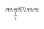
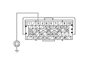
Disconnect the yaw rate-lateral acceleration sensor 4P connector.
-
Turn the ignition switch to ON (II), and read the HDS.
|
Does the HDS identify the vehicle?
|
|
YES
|
-
|
|
|
NO
|
-
|
-
With navigation system: Go to
Step 59
.
-
Without navigation system: Go to
Step 63
.
|
-
Turn the ignition switch to LOCK (0).
-
Reconnect the yaw rate-lateral acceleration sensor 4P connector.
-
Disconnect the navigation unit 32P connector.
-
Turn the ignition switch to ON (II), and read the HDS.
|
Does the HDS identify the vehicle?
|
-
Turn the ignition switch to LOCK (0).
-
Reconnect the navigation unit 32P connector (with navigation system) or the yaw rate-lateral acceleration sensor 4P connector (without navigation system).
-
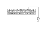
Disconnect EPS control unit connector D (28P).
-
Turn the ignition switch to ON (II), and read the HDS.
|
Does the HDS identify the vehicle?
|
-
Turn the ignition switch to LOCK (0).
-
Reconnect EPS control unit connector D (28P).
-
Disconnect SRS unit connector A (39P).
-
Turn the ignition switch to ON (II), and read the HDS.
|
Does the HDS identify the vehicle?
|
|
YES
|
-
|
|
|
NO
|
-
|
-
With driving support system: Go to
Step 71
.
-
|
-
Turn the ignition switch to LOCK (0).
-
Reconnect SRS unit connector A (39P).
-
Disconnect the LKAS control unit 26P connector.
-
Turn the ignition switch to ON (II), and read the HDS.
|
Does the HDS identify the vehicle?
|
-
Turn the ignition switch to LOCK (0).
-
Reconnect the LKAS control unit 26P connector.
-
Disconnect the ACC unit 20P connector.
-
Turn the ignition switch to ON (II), and read the HDS.
|
Does the HDS identify the vehicle?
|
-
Turn the ignition switch to LOCK (0).
-
Reconnect the ACC unit 20P connector.
-
Disconnect the E-pritensioner unit 14P connector.
-
Turn the ignition switch to ON (II), and read the HDS.
|
Does the HDS identify the vehicle?
|
|
|