A/T Assembly Installation

Special Tools Required

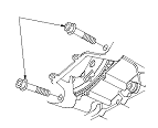
Engine support hanger
 AAR-T1256-J00

*
Subhanger stay
 07MAK-PY30100

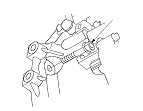
Subframe alignment pin
 070AG-SJAA10S
*: This special tool is available from Snap-on Tools    International, LLC.
NOTE: Use fender covers to avoid damaging painted surfaces.
R20A3 Engine Model
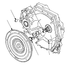
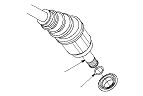
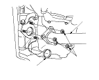
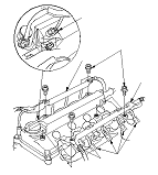
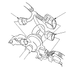
  1. Install a new O-ring (A) on the torque converter (B), then install the torque converter on the mainshaft (C).
  1. Install the 14 x 20 mm dowel pins (D) in the torque converter housing.
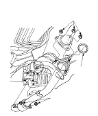
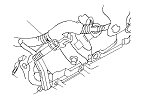
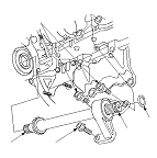
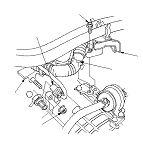
  1. Place the transmission on a jack, and raise the transmission to the engine level, then fit the transmission to the engine.

  1. Install the lower transmission housing mounting bolts.

  1. Install the rear transmission housing mounting bolt.

  1. Install the front transmission housing mounting bolt.

  1. Install the upper transmission housing mounting bolts.

  1. Install the front engine mount bracket (A) with new bolts, then install the vacuum hose bracket (B) on the front engine mount bracket.

  1. Install the rear engine mount bracket (A) with new bolts, then install the vacuum hose (B) on the hose clamp (C) at the mark (D).

  1. Install the rear engine mount (A) with new mounting bolt (B), and loosely tighten the mount bolt.

  1. Install new set ring (A) on the intermediate shaft (B).
  1. Clean the areas where the intermediate shaft contacts the transmission (differential) with solvent, and dry with compressed air. Apply ATF to the intermediate shaft splines (C), then install the intermediate shaft. Be sure not to allow dust or other foreign particles to enter the transmission.

  1. Install new set ring (A) on the left driveshaft (B).
  1. Clean the areas where the left driveshaft contacts the transmission (differential) with solvent, and dry with compressed air. Then install the left driveshaft. Be sure not to allow dust or other foreign particles to enter the transmission. Turn the steering knuckle fully outward, and slide the driveshaft into the differential until you feel its set ring fully engage the side gear.
  1. Slide the right driveshaft over the intermediate shaft splines until you feel the driveshaft fully engage the intermediate shaft set ring.

  1. Support the front subframe with a wood piece and a jack, and lift it up to the body.

  1. Loosely install new front subframe mounting bolts (A), front stiffener mounting bolts (B), and new rear stiffener mounting bolts (C).

  1. Loosely the transmission lower mount nuts (A).

  1. Install new transmission lower mount bolts.
  1. Tighten the transmission lower mounting bolts and the nuts to 44 N·m (4.5 kgf·m, 33 lbf·ft).

  1. Loosely tighten the subframe mounting bolt (A) in the right rear stiffener; insert the subframe alignment pin through the positioning slot (B) on the right rear stiffener, through the positioning hole (C) on the front subframe, and into the positioning hole on the body, then tighten the front subframe mounting bolt until the front subframe insulator contacts the body.
  1. Loosely tighten the front subframe mounting bolts in the right front stiffener, left front stiffener, and, left rear stiffener in the same manner in Step 22 .
  1. Reinsert the subframe alignment pin through the positioning slot on the right rear stiffener, through the positioning hole on the front subframe, and into the positioning hole on the body, then tighten the front subframe mounting bolt to the specified torque.
  1. Tighten the subframe mounting bolts in the right front stiffener, left front stiffener, and, left rear stiffener in the same manner in Step 24 .
  1. Tighten the right and left front subframe mounting bolts to the specified torque.
  1. Check that the positioning holes and slots are aligned using the subframe alignment pin.
  1. Tighten the rear and front stiffener mounting bolts to the specified torque.
  1. Remove the jack.

  1. Remove both front subframe mid-mount mounting bolts (A), and replace it.
  1. Tighten both front subframe mid-mount mounting bolts.

  1. Loosely tighten new upper transmission mount bracket mounting bolts (A) on the transmission housing.
  1. Secure the transmission ground cable (B) with the bolt.

  1. Loosely tighten a new front mount mounting bolt (A).
  1. Position the steering gearbox on the rear engine mount base bracket.

  1. Set the washers (A) between the steering gearbox and the rear engine mount base bracket.
  1. Tighten a new mounting bolt (B) and the washer (C) on the steering gearbox of the front driver's side.
  1. Tighten a new mounting bolt (D) and the washer on the steering gearbox of the front passenger's side.
  1. Tighten new mounting bolts (E) and the washer on the steering gearbox.

  1. Secure the rear engine mount (A) on the rear engine mount base bracket with new bolts (B), then tighten the rear engine mount mounting bolts to the specified torque.

  1. Apply molybdenum grease to the hole in the bushing (A) in the shift cable end (B). Attach the shift cable end to the selector control lever (C), then insert the control pin (D) into the selector control lever hole through the shift cable end, and secure the control pin with the spring clip (E). Do not bend the shift cable excessively.
  1. Install the shift cable bracket (F) with the bolts (G).
  1. Install the shift cable cover (H).

  1. Attach the torque converter to the drive plate with the eight bolts (A). Rotate the crankshaft pulley as necessary to tighten the bolts to 1/2 of the specified torque, then to the final torque, in a crisscross pattern. After tightening the last bolt, check that the crankshaft rotate freely.
  1. Install the torque converter cover (B).

  1. Connect the damper forks (A) and the lower arms (B) with new damper fork mounting bolts (C), the loosely tighten new mounting nuts (D).
  1. Connect the knuckle ball joints (E) on the lower arms. Loosely tighten new castle nuts (F).
    NOTE:
    • For headlight leveling system model: Be careful not to damage the suspension stroke sensor arm when connecting the knuckle ball joint from the left side lower arm.
    • Do not install the cotter pin (G) onto the castle nut until the castle nut tightened to the specified torque valve.


  1. Connect the vacuum hose (A) to the front engine mount and the hose clamp (B).

  1. Connect the suspension stroke sensor connector (A) if equipped.
  1. Remove the engine support hanger.

  1. Remove the subhanger stay (A) and the bolt (B), then install the harness holder bracket (C) on the cylinder head.

  1. Tighten the front engine mount bracket mounting bolt (A) to 54 N·m (5.5 kgf·m, 40 lbf·ft).
  1. Install the front engine mount stop (B) with new nuts.
  1. Tighten the rear engine mount bracket mounting bolt to 78 N·m (8.0 kgf·m, 58 lbf·ft).
  1. Tighten the transmission upper mount bracket mounting bolts to 59 N·m (6.0 kgf·m, 43 lbf·ft).

  1. Install the harness holder (A) on the bracket, and secure it with the bolts (B).
  1. Connect these harness connectors, and install the harness clamps:
    • Exhaust gas recirculation (EGR) valve connector (C)
    • Engine coolant temperature (ECT) sensor 1 connector (D)
    • Evaporative emission (EVAP) canister purge valve connector (E)
    • Camshaft position (CMP) sensor connector (F)
  1. Connect the breather hose (G) on the cylinder head cover, and secure the hose with the clip.
  1. Install the engine mount control solenoid valve (H) on the water outlet and secure it with the bolt.

  1. Secure each harness covers (A) with the bolts.
  1. Connect the ignition coil connectors (B) and the injector connectors (C).

  1. Install the engine cover.


  1. Connect these harness connectors:
    • 3rd clutch transmission fluid pressure switch connector (A)
    • A/T clutch pressure control solenoid valve B connector (B)
    • A/T clutch pressure control solenoid valve C connector (C)
    • Shift solenoid wire harness connector (D)
  1. Install the harness clamps (E) on the clamps brackets (F).

  1. Connect the output shaft (countershaft) speed sensor connector (A) and the input shaft (mainshaft) speed sensor connector (B).
  1. Install the transmission range switch connector (C).

  1. Connect the 2nd clutch transmission fluid pressure switch connector (A).
  1. Install the harness clamp (B) on the ATF filter bracket, and secure the clamp brackets (C) with the bolt and nut.

  1. Connect the A/T clutch pressure control solenoid valve A connector (A).
  1. Install the harness clamps (B) on the clamp brackets (C).
  1. Install the battery base.
  1. Install the air cleaner housing and the intake air duct.
  1. Install the PCM connectors, then install the PCM bracket.
  1. NOTE: Do not the test-driving until Step 88 .
  1. NOTE: Do not the service reminder system reset until Step 88 .

  1. Loosely tighten the front strut brace mounting nuts (A) on the front strut brace (B), and install the brake booster vacuum hose clamp (C) on the front strut brace.
  1. Set the parking brake. Start the engine, and shift the transmission through all gears three times.
  1. Check the shift lever operation, the A/T gear position indicator operation, and the shift cable adjustment.
  1. Place a floor jack under the lower arm, and raise the suspension to load it with the vehicle's weight. Do not place the jack against the ball joint pin of the knuckle.
    Tighten the damper fork mounting nuts while holding the mounting bolts to 64 N·m (6.5 kgf·m, 47 lbf·ft).
    Tighten the ball joint mounting nuts to 78−80 N·m (8.0−9.0 kgf·m, 58−65 lbf·ft). Install new cotter pins onto the castle nut, then bend the cotter pin ends.
  1. Tighten the front strut brace mounting nuts on top of the damper to 22 N·m (2.2 kgf·m, 16 lbf·ft).
  1. Install the front wheels.