A/T Assembly Removal

Special Tools Required

Engine support hanger
 AAR-T1256-J00

*
Subhanger stay
 07MAK-PY30100
*: This special tool is available from Snap-on Tools    International, LLC.
NOTE:
  • Use fender covers to avoid damaging painted surfaces.
  • To avoid damaging the wires and the terminals, unplug the wiring connectors carefully while holding the connector portion.
  • Mark all wiring and hoses to avoid misconnection. Also, be sure that they do not contact other wiring or hoses, or interfere with other parts.
  • Engine support hanger (AAR-T1256-J00) must be used with the side engine mount installed.
R20A3 Engine Model
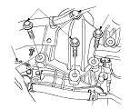
  1. Secure the hood in the wide open position with the support strut.
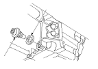
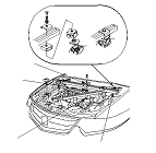
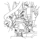
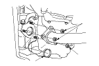
  1. Remove the harness clamps from the PCM bracket, then remove the two bolts securing the PCM bracket. Disconnect the PCM connectors from the PCM.
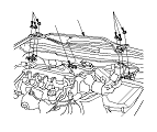
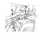
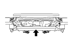
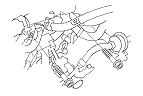
  1. Remove the brake booster vacuum hose clamp (A) and the nuts (B), then remove the strut brace (C).
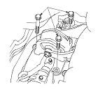
  1. Remove the air cleaner housing and the intake air duct.
  1. Remove the battery base.
  1. Raise the vehicle on a lift, and make sure it is securely supported.
  1. Remove the front wheels.
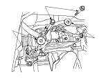
  1. Remove the splash shield.

  1. Remove the drain plug (A), and drain the automatic transmission fluid (ATF).
  1. Reinstall the drain plug with a new sealing washer (B).

  1. Disconnect the A/T clutch pressure control solenoid valve A connector (A).
  1. Remove the harness clamps (B) from the clamp brackets (C).

  1. Disconnect the 2nd clutch transmission fluid pressure switch connector (A), and remove the harness clamp (B), the bolt, and the nut securing the clamp brackets (C).

  1. Disconnect the transmission range switch connector (A).
  1. Disconnect the output shaft (countershaft) speed sensor connector (B) and the input shaft (mainshaft) speed sensor connector (C).

  1. Disconnect these harness connectors:
    • 3rd clutch transmission fluid pressure switch connector (A)
    • A/T clutch pressure control solenoid valve B connector (B)
    • A/T clutch pressure control solenoid valve C connector (C)
    • Shift solenoid wire harness connector (D)
  1. Remove the harness clamps (E) from the clamp brackets (F).

  1. Disconnect the ATF cooler hoses (A) from the ATF lines (B). Turn the end of the ATF cooler hoses up to prevent ATF from flowing out, then plug the ATF cooler hoses and the ATF lines.

  1. Remove the engine cover.

  1. Remove the bolts securing the harness covers (A) from the cylinder head cover.
  1. Disconnect the connectors (B) from the ignition coils (C) and the injectors (D).

  1. Remove the engine mount control solenoid valve (A) from the water outlet.
  1. Disconnect these harness connectors, and remove the harness clamps:
    • Exhaust gas recirculation (EGR) valve connector (B)
    • Engine coolant temperature (ECT) sensor 1 connector (C)
    • Evaporative emission (EVAP) canister purge valve connector (D)
    • Camshaft position (CMP) sensor connector (E)
  1. Remove the breather hose (F) from the cylinder head cover, then remove the bolts (G) securing the harness holder (H), and remove the harness holder from its bracket.

  1. Remove the harness holder bracket (A), and attach the subhanger stay (B) to the cylinder head bolt hole (C) with a 8 x 1.25−16 mm bolt (D).

  1. Install the engine support hanger (AAR-T1256-J00) to the vehicle, and attach the hook (A) to the subhanger stay (B). Tighten the wing nut (C) by hand, and lift and support the engine.

  1. Remove the upper transmission mount bracket bolts (A) from the transmission housing.
    NOTE: Do not remove the TORX bolt (B) from the upper transmission mount. If the TORX bolt is removed, the upper transmission mount must be replaced as an assembly.
  1. Remove the transmission ground cable (C) from the transmission housing.

  1. Remove the front engine mount stop (A), then remove the front engine mount bolt (B).

  1. Remove the rear engine mount bolts (A), from the rear engine mount bracket base.

  1. Remove the mounting bolts (A) from the steering gearbox EPS motor end side, and remove the washers (B).

  1. Remove the mounting bolts (A) from the steering gearbox pinion shaft side, and remove the washers (B).

  1. Remove the vacuum hose (A) from the front engine mount and the hose clamp (B).

  1. Remove the self-locking nuts (B) (8).
  1. Remove the exhaust pipe A and the gaskets (C).

  1. Remove the ATF cooler hose (A) from the ATF line (B). Turn the end of the ATF cooler hose up to prevent ATF from flowing out, then plug the hose and line.

  1. Remove the damper fork mounting nuts (A) while holding the mounting bolts (B).
  1. NOTE:
    For headlight leveling system model: Be careful not to damage the suspension stroke sensor arm when disconnecting the knuckle ball joint from the left side lower arm.

  1. Remove the torque converter cover (A), and remove the drive plate bolts (B) (8) while rotating the crankshaft pulley.

  1. Remove the shift cable cover (A).
  1. Remove the spring clip (B) and the control pin (C), and separate the shift cable end (D) from the selector control lever (E). Remove the two bolts securing the shift cable bracket (F).

  1. Remove the transmission lower mount bolts (A) from the transmission housing.

  1. Disconnect the suspension stroke sensor connector (A) if equipped.

  1. Loosen both front subframe mid-mount bolts (A).
  1. Hang the steering gearbox to the body with a strap.

  1. Support the front subframe with a wood piece and a jack.

  1. Remove the four bolts securing the stiffeners (A), and remove the four bolts securing the front subframe (B), and lower the front subframe.
    NOTE: Check that the front subframe is free of the vacuum hose, the ATF cooler hoses, and electrical wiring.

  1. Remove the left side driveshaft from the differential case and the right side driveshaft from the intermediate shaft. Coat all precision machined surfaces with clean engine oil, then put plastic bags over the driveshaft ends. Hang the driveshafts to the body with a strap.

  1. Remove the intermediate shaft. Coat all precision machined surfaces with clean engine oil, then put plastic bags over the intermediate shaft ends.

  1. Remove the rear engine mount bolt.

  1. Remove the vacuum hose (A) from the hose clamp, then remove the rear engine mount bracket (B).

  1. Remove the vacuum hose bracket (A) from the front engine mount bracket (B), then remove the front engine mount bracket (C).

  1. Remove the upper transmission housing mounting bolts.

  1. Remove the front transmission housing mounting bolt.

  1. Remove the rear transmission housing mounting bolt.
  1. Lower the transmission by loosening the wing nut of the engine support hanger, and tilt the engine just enough for the transmission to clear the side frame.
  1. Place a jack under the transmission.
  1. Check once again that all hoses and electrical wiring are disconnected and free from the transmission.

  1. Remove the lower transmission housing mounting bolts.
  1. Slide the transmission away from the engine to remove it from the vehicle.

  1. Remove the torque converter, the O-ring, and the dowel pins.
  1. Inspect the drive plate, and replace it if it is damaged.