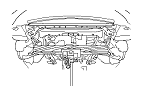
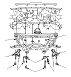
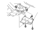
M/T Assembly Removal

Special Tools Required

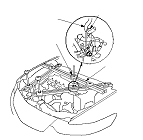
Engine support hanger
 AAR-T1256-J00

Subhanger stay
 07MAK-PY30100
R20A3 Engine Model
NOTE: Use fender covers to avoid damaging painted surfaces.
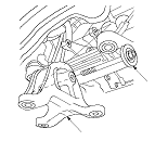
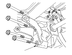
  1. Secure the hood in the wide open position with the support strut.
  1. Remove the ground cable clamp (A), upper battery base mounting bolts (B), and loosen the under battery base mounting bolts (C), then remove the battery base (D).

  1. Remove the clutch hose bracket (A) and the slave cylinder (B), then carefully move the slave cylinder out of the way to avoid bending the clutch line.
    NOTE:
    • Do not disconnect the clutch line joints.
    • Do not press the clutch pedal after the slave cylinder has been removed.

  1. Remove the nut (A), and release the clamp (B), then move the under-hood fuse/relay box (C) out of the way.

  1. Remove the lock pins (A) and the shift cable bracket bolts (B), then disconnect the shift cables (C) from the change lever assembly (D). Carefully remove both cables and the shift cable bracket (E) together to avoid bending the cables.

  1. Disconnect the output shaft (countershaft) speed sensor connector (A), and remove the harness clamp (B).
  1. Disconnect the back-up light switch connector (C) and the reverse lockout solenoid connector (D).

  1. Remove the harness holder bracket bolts (A).

  1. Remove the steering gearbox mounting bolts (A) and the top washers (B).
    NOTE: The washers (C) are put into top and under of the steering gearbox.
  1. Hung up both sides of the steering gearbox end securely to prevent damage the EPS harnesses.
Driver's side
Passenger's side

  1. Disconnect the EGR valve connector (A) and engine coolant temperature (ECT) sensor 1 connector (B), and remove the engine mount control solenoid valve mounting bolt (C).
  1. Remove the harness holder bolts (D), then move aside the harness holder (E) releasing the hooks (F).

  1. Remove the harness holder bracket (A).
  1. Attach the subhanger stay (B) with the hook (C) of the engine support hanger to threaded hole in the cylinder head using a 8 x 1.25 mm bolt (D).
    NOTE: Make sure the hook installing direction.

  1. Install the engine support hanger (A) with the hook (B) attached the subhanger stay (C) to the vehicle. Tighten the wing nut (D) by hand, and lift and support the engine.

  1. Remove the front engine mount stop (A), and the vacuum hose bracket bolt (B), then disconnect the vacuum hose (C).
  1. Remove the front engine mount bolt (D).

  1. Remove the rear engine mount bolts (A).

  1. Remove the transmission mount bracket bolts (A) from the transmission housing.
    NOTE: Do not remove the TORX bolt (B) from the upper transmission mount. If the TORX bolt is removed, the upper transmission mount must be replaced as an assembly.

  1. Remove the transmission hanger C from the transmission housing.

  1. Remove the upper transmission mounting bolts (A).
  1. Raise the vehicle on a lift, and make sure it is securely supported.

  1. Remove the ground cable (A) from the transmission housing.
  1. Remove both sides of the front subframe mid mount bolts (B).

  1. Remove the nuts (A) securing the lower transmission mount.

  1. Support the front suspension subframe with a piece of wood and a jack.

  1. Remove the four stiffeners mounting bolts (A), then remove the four front subframe mounting bolts (B) and stiffeners (C).
  1. Remove the front suspension subframe (D).
    NOTE: Pick up the steering gearbox mounting washers (E).

  1. Remove the rear engine mount (A).
    NOTE: The illustration shows equipped with a dynamic damper (B) type.

  1. Remove the rear engine mount bracket (A).

  1. Remove the front engine mount bracket (A).

  1. Remove the lower transmission mount (A).

  1. Separate the left driveshaft (A) from the differential. Pry the inboard joint (B) from the differential with a pryber.
    NOTE:
    • Do not pull on the driveshaft, or the inboard joint may come apart. Pull the inboard joint straight out to avoid damaging the oil seal.
    • Be careful not to damage the oil seal with the prybar.

  1. Separate the right driveshaft (A) from the intermediate shaft. Drive the inboard joint (B) off of the intermediate shaft using a drift and a hammer.
    NOTE: Do not pull on the driveshaft, or the inboard joint may come apart.

  1. Remove the clutch case cover (A).
  1. Securely support the transmission with a transmission jack.

  1. Remove the lower transmission mounting bolts.
  1. Pull the transmission away from the engine until the transmission mainshaft clears the clutch pressure plate.
  1. Slowly lower the transmission about 150 mm (6 in). Check once again that all hoses and electrical wiring are disconnected and free from the transmission then lower it completely.
Front side
Rear side