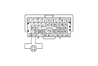
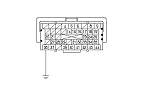
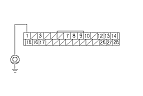
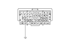
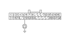
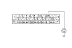
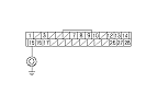
F-CAN Circuit Troubleshooting

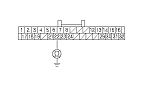
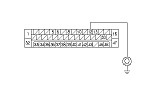
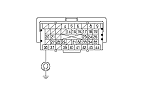
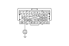
NOTE: Information marked with an asterisk ( * ) applies to the CANL line.
  1. Turn the ignition switch to LOCK (0).
  1. Jump the SCS line with the HDS.
  1. Disconnect ECM/PCM connector A (44P), then disconnect the HDS.
  1. Measure the resistance between ECM/PCM connector terminals A36 and A37.
Is there about 88-111 Ω?
YES -
Go to Step 33 .
NO -
Go to Step 5 .
  1. Disconnect these connectors:

  1. Check for continuity between ECM/PCM connector terminals A36 and A37.
Is there continuity?
YES -
Repair short in the wire between the ECM/PCM terminals A36 and A37 * .■
NO -
Go to Step 7 .

  1. Connect ECM/PCM connector terminal A36 to body ground with a jumper wire.

  1. Check for continuity between gauge control module 32P connector terminal No. 22 and body ground.
Is there continuity?
YES -
Go to Step 9 .
NO -
Repair open in the wire between the ECM/PCM (A36) and the gauge control module.■

  1. Check for continuity between VSA modulator-control unit 47P connector terminal No. 12 and body ground.
Is there continuity?
YES -
Go to Step 10 .
NO -
Repair open in the wire between the ECM/PCM (A36) and the VSA modulator-control unit.■

  1. Check for continuity between EPS control unit connector D (28P) terminal No. 1 and body ground.
Is there continuity?
YES -
Go to Step 11 .
NO -
Repair open in the wire between the ECM/PCM (A36) and the EPS control unit.■
  1. Remove the jumper wire from ECM/PCM connector A (44P).

  1. Connect ECM/PCM connector terminal A37 to body ground with a jumper wire.

  1. Check for continuity between gauge control module 32P connector terminal No. 21 and body ground.
Is there continuity?
YES -
Go to Step 14 .
NO -
Repair open in the wire between the ECM/PCM (A37) and the gauge control module.■

  1. Check for continuity between VSA modulator-control unit 47P connector terminal No. 13 and body ground.
Is there continuity?
YES -
Go to Step 15 .
NO -
Repair open in the wire between the ECM/PCM (A37) and the VSA modulator-control unit.■

  1. Check for continuity between EPS control unit connector D (28P) terminal No. 15 and body ground.
Is there continuity?
YES -
Go to Step 16 .
NO -
Repair open in the wire between the ECM/PCM (A37) and the EPS control unit.■
  1. Reconnect the gauge control module 32P connector.

  1. Measure the resistance between ECM/PCM connector terminals A36 and A37.
Is there about 108−132 Ω?
YES -
Go to Step 18 .
NO -
  1. Disconnect the gauge control module 32P connector.
  1. Reconnect the VSA modulator-control unit 47P connector.

  1. Measure the resistance between ECM/PCM connector terminals A36 and A37.
Is there about 2.34−2.86 kΩ?
YES -
Go to Step 21 .
NO -
  1. Disconnect the VSA modulator-control unit 46P connector.
  1. Reconnect the yaw rate-lateral acceleration sensor 4P connector.

  1. Measure the resistance between ECM/PCM connector terminals A36 and A37.
Is there about 2.34−2.86 kΩ?
YES -
Go to Step 24 .
NO -
  1. Disconnect the yaw rate-lateral acceleration sensor 4P connector.
  1. Reconnect EPS control unit connector D (28P).

  1. Measure the resistance between ECM/PCM connector terminals A36 and A37.
Is there about 2.34−2.86 kΩ?
YES -
Go to Step 27 .
NO -
  1. Disconnect EPS control unit connector D (28P).
  1. Reconnect SRS unit connector A (39P).

  1. Measure the resistance between ECM/PCM connector terminals A36 and A37.
Is there about 2.34−2.86 kΩ?
YES -
NO -
  1. Disconnect SRS unit connector A (39P).
  1. Reconnect the navigation unit 32P connector.

  1. Measure the resistance between ECM/PCM connector terminals A36 and A37.
Is there about 2.34−2.86 kΩ?
YES -
NO -
  1. Disconnect these connectors:

  1. Check for continuity between ECM/PCM connector terminal A36 and body ground.
Is there continuity?
YES -
Repair short in the wire between the ECM/PCM terminals A36 and the gauge control module, the VSA modulator-control unit, the yaw rate-lateral acceleration sensor, the EPS control unit, the SRS unit, the navigation unit (with navigation system), or the DLC.■
NO -
Go to Step 35 .

  1. Check for continuity between ECM/PCM connector terminal A37 and body ground.
Is there continuity?
YES -
Repair short in the wire between the ECM/PCM terminals A37 and the gauge control module, the VSA modulator-control unit, the yaw rate-lateral acceleration sensor, the EPS control unit, the SRS unit, the navigation unit (with navigation system), or the DLC.■
NO -
Go to Step 36 .
  1. Reconnect all connectors.
  1. Disconnect the gauge control module 32P connector.
  1. Turn the ignition switch to ON (II), and read the HDS.
Does the HDS identify the vehicle?
YES -
NO -
Go to Step 40 .
  1. Turn the ignition switch to LOCK (0).
  1. Reconnect the gauge control module 32P connector.
  1. Disconnect the VSA modulator-control unit 47P connector.
  1. Turn the ignition switch to ON (II), and read the HDS.
Does the HDS identify the vehicle?
YES -
NO -
Go to Step 44 .
  1. Turn the ignition switch to LOCK (0).
  1. Reconnect the VSA modulator-control unit 47P connector.
  1. Disconnect the yaw rate-lateral acceleration sensor 4P connector.
  1. Turn the ignition switch to ON (II), and read the HDS.
Does the HDS identify the vehicle?
YES -
NO -
Go to Step 48 .
  1. Turn the ignition switch to LOCK (0).
  1. Reconnect the yaw rate-lateral acceleration sensor 4P connector.
  1. Disconnect EPS control unit connector D (28P).
  1. Turn the ignition switch to ON (II), and read the HDS.
Does the HDS identify the vehicle?
YES -
NO -
Go to Step 52 .
  1. Turn the ignition switch to LOCK (0).
  1. Reconnect EPS control unit connector D (28P).
  1. Disconnect SRS unit connector A (39P).
  1. Turn the ignition switch to ON (II), and read the HDS.
Does the HDS identify the vehicle?
YES -
NO -
  1. Turn the ignition switch to LOCK (0).
  1. Reconnect SRS unit connector A (28P).
  1. Disconnect the navigation unit 32P connector.
  1. Turn the ignition switch to ON (II), and read the HDS.
Does the HDS identify the vehicle?
YES -
NO -