|
NOTE: Make sure the HDS and the DLC cable of the HDS is normal.
-
Turn the ignition switch to LOCK (0).
-
NOTE: Make sure the HDS is properly connected to the DLC.
-
Turn the ignition switch to ON (II), and read the HDS.
|
Does the HDS identify the vehicle?
|
-
Check for Temporary DTCs or DTCs in the PGM-FI system with the HDS.
|
Are any Temporary DTCs or DTCs indicated?
|
|
YES
|
-
|
Go to the indicated DTC's troubleshooting.■
|
|
NO
|
-
|
-
If the HDS does not communicate with the SRS system, go to
Step 5
.
-
If the HDS does not communicate with the VSA system, go to
Step 7
.
-
If the HDS does not communicate with the EPS system, go to
Step 9
.
-
If the HDS does not communicate with the IMMOBI (immobilizer) system, go to
Step 11
.
-
If the HDS does not communicate with the BODY ELECTRICAL system, go to
Step 13
.
|
-
Turn the ignition switch to LOCK (0).
-
Turn the ignition switch to ON (II), and watch the SRS indicator.
|
Does the SRS indicator stay on?
|
-
Turn the ignition switch to LOCK (0).
-
Turn the ignition switch to ON (II), and watch the VSA indicator.
|
Does the VSA indicator stay on?
|
-
Turn the ignition switch to LOCK (0).
-
Turn the ignition switch to ON (II), and watch the EPS indicator.
|
Does the EPS indicator stay on?
|
-
Turn the ignition switch to LOCK (0).
-
Turn the ignition switch to ON (II), and watch the immobilizer indicator.
|
Does the immobilizer indicator stay on or flash?
|
-
-
Check the gauge display.
-
Turn the ignition switch to LOCK (0).
-
Disconnect the HDS from the DLC.
-
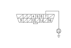
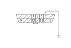
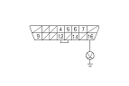
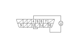
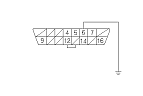
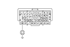
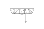
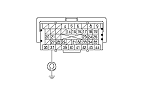
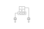
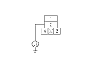
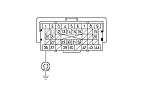
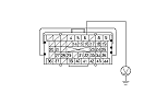
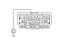
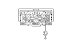
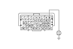
Check for continuity between DLC terminal No. 7 and body ground.
-
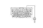
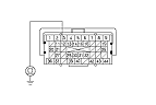
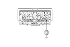
Continue to check for continuity between DLC terminal No. 7 and body ground while disconnecting these connectors, one at a time:
-
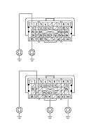
SRS unit connector A (39P)
-
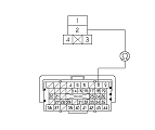
VSA modulator-control unit 47P connector
-
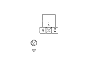
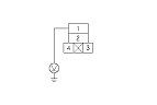
EPS control unit connector D (28P)
-
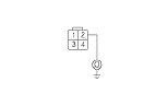
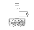
Immobilizer-keyless control unit 7P connector
-
Audio unit 24P connector
-
Driver's under-dash fuse/relay box Q (20P)
|
Does continuity go away when one of the above components is disconnected?
|
|
YES
|
-
|
Replace the part that caused an open when it was disconnected.■
|
|
NO
|
-
|
Repair short in the wire between the DLC (K-line) and the VSA modulator-control unit, the SRS unit, the EPS control unit, the immobilizer-keyless control unit, the audio unit, or the driver's under-dash fuse/relay box.■
|
|