How to Troubleshoot the A/T System

How to Check for DTCs with the Honda Diagnostic System (HDS)
When the powertrain control module (PCM) senses an abnormality in the input or output system, the D indicator (A) in the gauge control module (B) will usually blink.

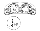
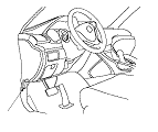
When the Honda Diagnostic System (HDS) is connected to the data link connector (DLC) (A) located under the driver's side of the dashboard, it will indicate the diagnostic trouble code (DTC) when the ignition switch is turned to ON (II) and the appropriate menu is selected.
If the D indicator or the malfunction indicator lamp (MIL) has been reported on, or if a driveability problem is suspected, follow this procedure:
  1. Connect the HDS to the DLC. (See the HDS user's manual for specific instructions.)
  1. Turn the ignition switch to ON (II). Make sure the HDS communicates with the PCM. If it does not, go to the DLC circuit troubleshooting; R20A3 engine model, K24Z3 engine model.
  1. Select A/T system, and observe the DTC in the DTCs MENU on the HDS screen.
  1. Record the freeze data and the on-board snapshots for all fuel and emissions DTCs and A/T DTCs.
  1. If there is a fuel and emissions DTC, first check the fuel and emissions system as indicated by the DTC.
  1. Clear the DTC and the data.
  1. Drive the vehicle for several minutes under the same conditions as those indicated by the freeze data, and then recheck for a DTC. If the A/T DTC returns, go to the indicated DTC's troubleshooting. If the DTC does not return, there was an intermittent problem within the circuit. Make sure all pins and terminals in the circuit are tight.

Symptom Troubleshooting Versus DTC Troubleshooting
Some symptoms will not trigger DTCs or cause the D indicator to blink. If the MIL was reported ON or the D indicator has been blinking, check for DTCs. If the vehicle has an abnormal symptom, and there are no DTCs stored, do the symptom troubleshooting. Check the list of probable cause(s) for the symptom, in the sequence listed, until you find the problem.

How to Troubleshoot Circuits at the PCM Connectors
NOTE: The PCM overwrites data and monitors the EVAP system for up to about 30 minutes after the ignition switch is turned to LOCK (0). Jumping the SCS line after turning the ignition switch to LOCK (0) cancels this function. Disconnecting the PCM during this function, without jumping the SCS line first, can damage the PCM.
  1. Jump the SCS line with the HDS.
  1. Disconnect PCM connectors A, B, and C.
    NOTE: PCM connectors A, B, and C have symbols (A=□, B=△, C=○) embossed on them for identification.

  1. When diagnosis/troubleshooting is done at the PCM connector, use the terminal test port (A) above the terminal you need to check.

  1. Connect one side of the patch cord (A) terminals to a commercially available digital multimeter (B), and connect the other side of the patch cord terminals to a commercially available banana jack (Pomona Electronics Tool No. 3563 or equivalent) (C).
  1. Gently insert the pin probe (male) into the terminal test port from the terminal side. Do not force the tips into the terminals.
  • For accurate results, always use the pin probe (male).
  • To prevent damage to the connector terminals, do not insert test equipment probes, paper clips, or other substitutes as they can damage the terminals. Damaged terminals cause a poor connection and an incorrect measurement.
  • Do not puncture the insulation on a wire. Punctures can cause poor or intermittent electrical connections.

Clear A/T DTCs Procedure
  1. Connect the HDS to the DLC (A) located under the driver's side of the dashboard.
  1. Turn the ignition switch to ON (II).
  1. Make sure the HDS communicates with the PCM. If it does not, go to the DLC circuit troubleshooting; R20A3 engine model, K24Z3 engine model.
  1. Clear the DTC(s) on the HDS screen.

OBD Status
The OBD status shows the current system status of each DTC and all of the parameters. This function is used to see if the technician's repair was successfully completed. The results of diagnostic tests for the DTC are displayed as:
  • PASSED: The on-board diagnosis has successfully completed.
  • FAILED: The on-board diagnosis has finished but failed.
  • NOT COMPLETED: The on-board diagnosis was running but is out of the enable conditions of the DTC.

How to End a Troubleshooting Session (required after any troubleshooting)
NOTE: Reset the PCM with the HDS while the engine is stopped.
  1. Turn the ignition switch to LOCK (0).
  1. Turn the ignition switch to ON (II), and wait for 30 seconds.
  1. Turn the ignition switch to LOCK (0), and disconnect the HDS from the DLC.
  1. Do the PCM idle learn procedure; R20A3 engine model, K24Z3 engine model.
  1. Start the engine with the shift lever in P or N, and warm it up to normal operating temperature (the radiator fan comes on).
  1. To verify that the problem is repaired, test-drive the vehicle for several minutes at speeds over 50 km/h (31 mph) or under the same conditions as those indicated by the freeze data.

Substituting the PCM
Special Tools Required
  • Honda diagnostic system (HDS)
  • Honda interface module (HIM)
  • HDS pocket tester
Use any one of these update tools.
NOTE: Use this procedure when you have to substitute a known-good PCM during troubleshooting procedure.
  1. Connect the HDS to the data link connector (DLC) (A) located under the driver's side of the dashboard.
  1. Turn the ignition switch to ON (II).
  1. Make sure the HDS communicates with the PCM. If it does not, go to the DLC circuit troubleshooting; R20A3 engine model, K24Z3 engine model.
  1. Jump the SCS line with the HDS.
  1. Turn the ignition switch to LOCK (0).

  1. Remove the PCM cover (A).
  1. Remove the battery setting plate (B), and re-position the battery away from the PCM.
    NOTE: Do not disconnect the battery terminals.

  1. Remove the bolts (D).
  1. Disconnect PCM connectors A, B, and C, then remove the PCM assembly (E).
    NOTE: PCM connectors A, B, and C have symbols (A=□, B=△, C=○) embossed on them for identification.
  1. Install a known-good PCM in the reverse order of removal.
  1. Turn the ignition switch to ON (II).
    NOTE: DTC P0630 ‘‘VIN Not Programmed or Mismatch'' may be stored because the VIN has not been programmed into the PCM; ignore it, and continue this procedure.
  1. Manually input the VIN to the PCM with the HDS.
  1. Select the IMMOBI SYSTEM with the HDS.
  1. Enter the immobilizer code using the PCM replacement procedure in the HDS; it allows you to start the engine.
  1. Select the PGM-FI system and reset the PCM with the HDS; R20A3 engine model, K24Z3 engine model.
  1. Update the PCM if it does not have the latest software; R20A3 engine model, K24Z3 engine model.
  1. Do the PCM idle learn procedure; R20A3 engine model, K24Z3 engine model.
  1. Do the CKP pattern learn procedure; R20A3 engine model, K24Z3 engine model.

Failure Reproduction Technique
Be careful to the following points while the vehicle is raising on a lift for the test-drive.
  • Disable the VSA by pressing the VSA OFF switch.
  • A DTC or a Temporary DTC may be set during the test-driving. Check for DTCs, and clear them as needed.