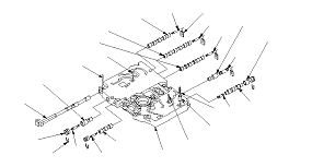
A/T Main Valve Body Disassembly, Inspection, and Reassembly
-
Clean all parts thoroughly in solvent, and dry them with compressed air. Blow out all passages.
-
Do not use a magnet to remove the check balls, it may magnetize the balls.
-
Inspect the valve body for scoring and damage.
-
-
Coat all parts with ATF during assembly.
SPRING SPECIFICATIONS
|
Springs
|
Standard (New)-Unit: mm (in.)
|
|
Wire Diameter
|
O.D.
|
Free Length
|
No. of Coils
|
|
A
|
Shift valve A spring
|
0.8 (0.031)
|
5.6 (0.220)
|
28.1 (1.106)
|
15.9
|
|
B
|
Shift valve B spring
|
0.8 (0.031)
|
5.6 (0.220)
|
28.1 (1.106)
|
15.9
|
|
C
|
Shift valve C spring
|
0.8 (0.031)
|
5.6 (0.220)
|
28.1 (1.106)
|
15.9
|
|
D
|
Relief valve spring
|
1.0 (0.039)
|
9.6 (0.378)
|
34.1 (1.343)
|
10.2
|
|
E
|
Lock-up control valve spring
|
0.65 (0.026)
|
7.1 (0.280)
|
23.1 (0.909)
|
12.7
|
|
F
|
Cooler check valve spring
|
0.85 (0.033)
|
6.6 (0.260)
|
27.0 (1.063)
|
11.3
|
|
G
|
Servo control valve spring
|
0.7 (0.028)
|
6.6 (0.260)
|
35.7 (1.406)
|
17.2
|
|
H
|
Shift valve E spring
|
0.8 (0.031)
|
5.6 (0.220)
|
28.1 (1.106)
|
15.9
|
|
|
-
Clean all parts thoroughly in solvent, and dry them with compressed air. Blow out all passages.
-
Do not use a magnet to remove the check balls, it may magnetize the balls.
-
Inspect the valve body for scoring and damage.
-
-
Coat all parts with ATF during assembly.
|
|
|
SPRING SPECIFICATIONS
|
Springs
|
Standard (New)-Unit: mm (in.)
|
|
Wire Diameter
|
O.D.
|
Free Length
|
No. of Coils
|
|
A
|
Shift valve A spring
|
0.8 (0.031)
|
5.6 (0.220)
|
28.1 (1.106)
|
15.9
|
|
B
|
Shift valve B spring
|
0.8 (0.031)
|
5.6 (0.220)
|
28.1 (1.106)
|
15.9
|
|
C
|
Shift valve C spring
|
0.8 (0.031)
|
5.6 (0.220)
|
28.1 (1.106)
|
15.9
|
|
D
|
Relief valve spring
|
1.0 (0.039)
|
9.6 (0.378)
|
34.1 (1.343)
|
10.2
|
|
E
|
Lock-up control valve spring
|
0.65 (0.026)
|
7.1 (0.280)
|
23.1 (0.909)
|
12.7
|
|
F
|
Cooler check valve spring
|
0.85 (0.033)
|
6.6 (0.260)
|
27.0 (1.063)
|
11.3
|
|
G
|
Servo control valve spring
|
0.7 (0.028)
|
6.6 (0.260)
|
35.7 (1.406)
|
17.2
|
|
H
|
Shift valve E spring
|
0.8 (0.031)
|
5.6 (0.220)
|
28.1 (1.106)
|
15.9
|
|