A/T Secondary Shaft 1st Gear Axial Clearance Inspection

Special Tools Required

Bearing driver attachment 42 mm
 07QAD-P0A0100
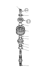
  1. Install the thrust needle bearing (A), the needle bearing (B), 1st gear (C), the thrust needle bearing (D), the 40 x 51.5 mm thrust washer (E), the 1st/3rd clutch (F), and the 3rd gear collar (G) on the secondary shaft (H). Do not install the O-rings during inspection.
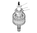
  1. Install the idler gear (I), then install the transmission housing bearing (J) on the idler gear using the 42 mm bearing driver attachment and a press.
  1. Install the conical spring washer (K) and the locknut (L), then tighten the locknut to 29 N·m (3.0 kgf·m, 22 lbf·ft).

  1. Turn the secondary shaft assembly upside down, and set the dial indicator (A) on 1st gear (B).

  1. Lift 1st gear (A) up while holding the secondary shaft, and use the dial indicator (B) to read 1st gear axial clearance.
  1. Measure the 1st gear axial clearance in at least three places while moving 1st gear. Use the average as the actual clearance.
    Standard:
    0.04−0.12 mm (0.002−0.005 in.)

  1. If the clearance is out of standard, remove the 40 x 51.5 mm thrust washer and measure its thickness.
  1. Select and install a new thrust washer, then recheck.

    THRUST WASHER, 40 x 51.5 mm

    No.
    Part Number
    Thickness
    1
    90503-RCT-000
    4.80 mm (0.189 in.)
    2
    90504-RCT-000
    4.85 mm (0.191 in.)
    3
    90505-RCT-000
    4.90 mm (0.193 in.)
    4
    90506-RCT-000
    4.95 mm (0.195 in.)
    5
    90507-RCT-000
    5.00 mm (0.197 in.)
    6
    90508-RCT-000
    5.05 mm (0.199 in.)

  1. After replacing the thrust washer, make sure the clearance is within standard.
  1. Disassemble the shaft and the gears.