A/T Clutch Wave-plate Phase Difference Inspection

  1. Place the clutch wave-plate (A) on a surface plate, and set a dial indicator (B) on the wave-plate.
  1. Find the bottom (C) of a phase difference of the wave-plate, zero the dial indicator and make a reference mark on the bottom of the wave-plate.
  1. Rotate the wave-plate about 60-degrees apart from the bottom while holding the wave-plate by its circumference. The dial indicator should be at the top (D) of a phase difference. Do not rotate the wave-plate while holding its surface, always rotate it with holding its circumference.
  1. Read the dial indicator. The dial indicator reads the phase difference (E) of the wave-plate between the bottom and the top.
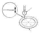
    Standard Phase Difference
    R20A3 Engine Model:
    1st Clutch:
    0.07−0.20 mm (0.003−0.008 in.)
    2nd Clutch:
    0.07−0.20 mm (0.003−0.008 in.)
    3rd Clutch:
    0.07−0.20 mm (0.003−0.008 in.)
    4th Clutch:
    0.10−0.20 mm (0.004−0.008 in.)
    5th Clutch:
    0.10−0.20 mm (0.004−0.008 in.)
    K24Z3 Engine Model:
    1st Clutch:
    0.15−0.25 mm (0.006−0.010 in.)
    2nd Clutch:
    0.1−0.2 mm (0.004−0.008 in.)
    3rd Clutch:
    0.1−0.2 mm (0.004−0.008 in.)
    4th Clutch:
    0.1−0.2 mm (0.004−0.008 in.)
    5th Clutch:
    0.1−0.2 mm (0.004−0.008 in.)


  1. Rotate the wave-plate about 60-degrees. The dial indicator should be at the bottom of a phase difference (F), and zero the dial indicator.
  1. Measure the phase difference at the top (G) of the wave-plate by following Step 3 thru 5.
  1. Measure the phase difference at the bottom (H) and the top (I) of the wave-plate by following Step 5 thru 6.
  1. If two of the three measurements are within the standard, the wave-plate is OK. If two of the three measurements are out of the standard, replace the wave-plate.