A/T Pressure Test

Special Tools Required

A/T oil pressure gauge set
 07406-0020005
NOTE:
  • Disable the VSA by pressing the VSA OFF switch.
  • ABS or VSA DTC(s) may come on during the test-drive. If the ABS or VSA DTC(s) come on, clear the DTC(s) with the HDS.
  1. Raise the vehicle on a lift, or apply the parking brake, block the rear wheels, and raise the front of the vehicle. Make sure it is securely supported.
  1. Allow the front wheels to rotate freely.
  1. Remove the splash shield.
  1. Connect the HDS to the DLC (A) located under the driver's side of the dashboard.
  1. Turn the ignition switch to ON (II). Make sure the HDS communicates with the PCM. If it does not, go to the DLC circuit troubleshooting; R20A3 engine model, K24Z3 engine model.

  1. Connect the A/T oil pressure gauge to the line pressure inspection port (A). Do not allow dust or other foreign particles to enter the port while connecting the gauge.
  1. Start the engine, and warm it up to normal operating temperature (the radiator fan comes on).
  1. Hold the engine speed at 2,000 rpm (min −1 ) with the shift lever in P or N.
  1. Measure the line pressure at the line pressure inspection port.
    NOTE: Higher pressure may be indicated if measurements are made in shift lever positions other than P or N.

    R20A3 Engine Model:

    Pressure
    Fluid Pressure
    Standard
    Service Limit
    Line (A)
    902−960 kPa (9.2−9.8 kgf/cm 2 , 131−139 psi)
    853 kPa (8.7 kgf/cm 2 , 124 psi)


    K24Z3 Engine Model:

    Pressure
    Fluid Pressure
    Standard
    Service Limit
    Line (A)
    927−985 kPa (9.45−10.05 kgf/cm 2 , 134−143 psi)
    877 kPa (8.95 kgf/cm 2 , 127 psi)

  1. Turn the engine off, then disconnect the A/T oil pressure gauge from the line pressure inspection port.
  1. Install the sealing bolt in the line pressure inspection port with a new sealing washer, and tighten the sealing bolt to 18 N·m (1.8 kgf·m, 13 lbf·ft). Do not reuse the old sealing washer.

  1. Connect the A/T oil pressure gauge to the 1st clutch pressure inspection port (B).

  1. Remove the intake air duct and the air cleaner housing, and connect the A/T oil pressure gauge to the 2nd clutch pressure inspection port (C). Then temporarily install the air cleaner housing and the intake air duct.
  1. Start the engine, and shift to S.
  1. Shift to 1st gear by pulling the paddle shifter + (upshift switch), and measure the 1st clutch pressure at the 1st clutch pressure inspection port (B) while holding the engine speed at 2,000 rpm (min −1 ).
  1. Shift up to 2nd gear by pulling the paddle shifter + (upshift switch), and measure the 2nd clutch pressure at the 2nd clutch pressure inspection port (C) while holding the engine speed at 2,000 rpm (min −1 ).

    R20A3 Engine Model:

    Pressure
    Fluid Pressure
    Standard
    Service Limit
    1st clutch (B)
    2nd clutch (C)
    892−970 kPa (9.1−9.9 kgf/cm 2 , 129−141 psi)
    843 kPa (8.6 kgf/cm 2 , 122 psi)


    K24Z3 Engine Model:

    Pressure
    Fluid Pressure
    Standard
    Service Limit
    1st clutch (B)
    2nd clutch (C)
    917−995 kPa (9.35−10.15 kgf/cm 2 , 133−144 psi)
    867 kPa (8.85 kgf/cm 2 , 126 psi)

  1. Turn the engine off, then disconnect the A/T oil pressure gauges from the 1st clutch pressure and the 2nd clutch pressure inspection ports.
  1. Install the sealing bolts in the 1st clutch pressure and the 2nd clutch pressure inspection ports with new sealing washers, and tighten the sealing bolts to 18 N·m (1.8 kgf·m, 13 lbf·ft). Do not reuse the old sealing washers.

  1. Connect the A/T oil pressure gauge to the 3rd clutch pressure inspection port (D) and the 5th clutch pressure inspection port (F).

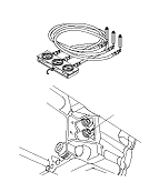
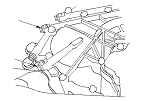
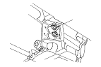
  1. Connect the A/T oil pressure gauge to the 4th clutch pressure inspection port (E).
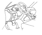
  1. Start the engine, and shift in the sequential shift mode in S.
  1. Upshift to 3rd gear by pulling the paddle shifter + (upshift switch), and measure the 3rd clutch pressure at the 3rd clutch pressure inspection port (D) while holding the engine speed at 2,000 rpm (min −1 ).
  1. Upshift to 4th gear by pulling the paddle shifter + (upshift switch), and measure the 4th clutch pressure at the 4th clutch pressure inspection port (E) while holding the engine speed at 2,000 rpm (min −1 ).
  1. Upshift to 5th gear by pulling the paddle shifter + (upshift switch), and measure the 5th clutch pressure at the 5th clutch pressure inspection port (F) while holding the engine speed at 2,000 rpm (min −1 ).

    R20A3 Engine Model:

    Pressure
    Fluid Pressure
    Standard
    Service Limit
    3rd clutch (D)
    4th clutch (E)
    5th clutch (F)
    892−970 kPa (9.1−9.9 kgf/cm 2 , 129−141 psi)
    843 kPa (8.6 kgf/cm 2 , 122 psi)


    K24Z3 Engine Model:

    Pressure
    Fluid Pressure
    Standard
    Service Limit
    3rd clutch (D)
    4th clutch (E)
    5th clutch (F)
    917−995 kPa (9.35−10.15 kgf/cm 2 , 133−144 psi)
    867 kPa (8.85 kgf/cm 2 , 126 psi)

  1. Bring the engine back to an idle, then apply the brake pedal to stop the wheels from rotating.
  1. Shift to R, then release the brake pedal. Raise the engine speed to 2,000 rpm (min −1 ), and measure 4th clutch pressure at the 4th clutch pressure inspection port (E).

    R20A3 Engine Model:

    Pressure
    Fluid Pressure
    Standard
    Service Limit
    4th clutch (E) in R
    892−970 kPa (9.1−9.9 kgf/cm 2 , 129−141 psi)
    843 kPa (8.6 kgf/cm 2 , 122 psi)


    K24Z3 Engine Model:

    Pressure
    Fluid Pressure
    Standard
    Service Limit
    4th clutch (E) in R
    917−995 kPa (9.35−10.15 kgf/cm 2 , 133−144 psi)
    867 kPa (8.85 kgf/cm 2 , 126 psi)

  1. Turn the engine off, then disconnect the A/T oil pressure gauges from the 3rd, 4th, and 5th clutch pressure inspection ports.
  1. Install the sealing bolts in the 3rd, 4th, and 5th clutch pressure inspection ports with new sealing washers, and tighten the sealing bolts to 18 N·m (1.8 kgf·m, 13 lbf·ft). Do not reuse the old sealing washers.
  1. If the pressures are out of the service limit, problems and probable causes are listed in the table.
    Problem
    Probable causes
    No or low line pressure
    • Torque converter
    • ATF pump
    • Regulator valve
    • Torque converter check valve
    • Clogged ATF strainer
    No or low 1st clutch pressure
    • 1st clutch
    • O-rings
    No or low 2nd clutch pressure
    • 2nd clutch
    • O-rings
    No or low 3rd clutch pressure
    • 3rd clutch
    • O-rings
    No or low 4th clutch pressure
    • 4th clutch
    • O-rings
    No or low 5th clutch pressure
    • 5th clutch
    • O-rings
    No or low 4th clutch pressure in R
    • Servo valve
    • 4th clutch
    • O-rings

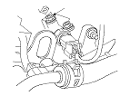
  1. Install the air cleaner housing and the intake air duct.
  1. Install the splash shield.