A/T Shift Solenoid Valve Test

  1. Connect the HDS to the DLC (A) located under the driver's side of the dashboard.
  1. Turn the ignition switch to ON (II). Make sure the HDS communicates with the PCM. If it does not, go to the DLC circuit troubleshooting; R20A3 engine model, K24Z3 engine model.
  1. Select Shift Solenoid Valves A, B, C, D, and E in the Miscellaneous Test Menu with the HDS.
  1. Check that shift solenoid valves A, B, C, D, and E operate with the HDS. A clicking sound should be heard.
    • If a clicking sound is heard, the valves are OK. The test is complete, disconnect the HDS.
    • If no clicking sound is heard, go to Step 5 .
  1. Raise the vehicle on a lift, or apply the parking brake, block the rear wheels, and raise the front of the vehicle. Make sure it is securely supported.
  1. Remove the splash shield.

  1. Disconnect the shift solenoid wire harness connector.
  1. Measure the resistance:
    • No. 1 terminal: Shift solenoid valve C
    • No. 2 terminal: Shift solenoid valve B
    • No. 3 terminal: Shift solenoid valve E
    • No. 5 terminal: Shift solenoid valve A
    • No. 8 terminal: Shift solenoid valve D
    Standard:
    12−25 Ω

    • If the resistance is within the standard, go to Step 9 .
    • If the resistance is out of standard, go to Step 10 .
  1. Connect a jumper wire from the negative battery terminal to body ground, and connect another jumper wire from the positive battery terminal to each shift solenoid wire harness connector terminal individually. A clicking sound should be heard.
    • If a clicking sound is heard, the valves are OK. The test is complete, reconnect the connector, and install all removed parts.
    • If no clicking sound is heard, go to Step 10 .

  1. Remove the drain plug (A), and drain the transmission fluid (ATF).
  1. Reinstall the drain plug with a new sealing washer (B).
  1. Remove the battery base.
  1. Remove the air cleaner housing and the intake air duct.

  1. Remove the ATF dipstick, then remove the bolts (A) securing the ATF cooler line (B).
  1. Remove the harness clamps (C) from the clamp brackets.
  1. Remove the bolts (D) securing the ATF dipstick guide tube (E), and remove the ATF dipstick guide tube.

  1. Remove the shift solenoid valve cover (A), the dowel pins (B), and the gasket (C).

  1. Disconnect the connectors from the shift solenoid valves.
  1. Measure the resistance of each shift solenoid valve between the connector terminals and body ground.
    Standard:
    12−25 Ω

    • If the resistance is within the standard, go to Step 21 .
    • If the resistance is out of standard, go to Step 25 .
  1. Connect a jumper wire from the negative battery terminal to body ground, and connect another jumper wire from the positive battery terminal to each solenoid valve terminal individually.
    • If a clicking sound is heard, go to Step 22 .
    • If no clicking sound is heard, go to Step 25 .

  1. Disconnect the shift solenoid wire harness connector (A), then remove the bolt (B) securing the shift solenoid wire harness (C) from the transmission housing.
  1. Remove the shift solenoid wire harness.
  1. Install a new O-ring (D) on a new shift solenoid wire harness, then install the shift solenoid wire harness in the transmission housing. Secure the shift solenoid wire harness with the bolt, go to Step 31 .

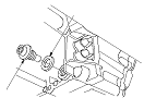
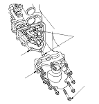
  1. Remove the shift solenoid valve mounting bolts (F), then hold the shift solenoid valve body, and remove the shift solenoid valves.
    NOTE: Do not hold the shift solenoid valve connector to remove the shift solenoid valves.
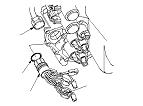
  1. Install new O-rings (two O-rings per shift solenoid valve) (G) on the shift solenoid valves.
    NOTE: A new shift solenoid valve comes with new O-rings. If you install a new shift solenoid valve, use the O-rings provided with it.
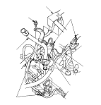
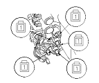
  1. Install shift solenoid valve C (brown connector), shift solenoid valve D (black connector), and shift solenoid valve E (black connector) by holding the shift solenoid valve body; make sure the mounting bracket contacts the servo body.
    NOTE: Do not hold the shift solenoid valve connector to install the shift solenoid valve. Be sure to hold the shift solenoid valve body.
  1. Install shift solenoid valve B (brown connector) by holding the shift solenoid valve body; make sure the mounting bracket contacts the bracket of shift solenoid valve E.
  1. Install shift solenoid valve A (brown connector) by holding the shift solenoid valve body; make sure the mounting bracket contacts the bracket of shift solenoid valve D.
    NOTE: Do not install shift solenoid valves A and B before installing shift solenoid valves D and E. If shift solenoid valves A and B are installed before installing shift solenoid valves D and E, it may damage the hydraulic control system.
  1. Secure shift solenoid valves B and E with the bolt, then secure shift solenoid valves A and E with the bolt.
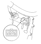
  1. Connect the shift solenoid harness terminals to the shift solenoid valves:
    • BLU wire connector to shift solenoid valve A.
    • ORN wire connector to shift solenoid valve B.
    • GRN wire connector to shift solenoid valve C.
    • YEL, WHT, and WHT wire connector to shift solenoid valve D.
    • RED wire connector to shift solenoid valve E.
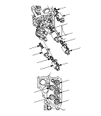
  1. Install a new gasket, the dowel pins, and the shift solenoid valve cover.
  1. Install a new O-ring on the ATF dipstick guide tube, then install the guide tube. Secure the guide tube with the bolts.
  1. Check the shift solenoid wire harness connector for rust, dirt, or oil, clean if necessary, then connect the connector securely.
  1. Secure the ATF cooler line with the bolts.
  1. Install the harness clamp on the clamp brackets.
  1. Install the battery base.
  1. Install the intake air duct and the air cleaner housing.
  1. Install the splash shield.
  1. Install the left front wheel.
  1. NOTE: Do not the test-driving until Step 42 .